Fire prevention system

a technology of fire prevention and fire prevention, applied in the field of fire prevention systems, can solve the problems of significant loss or severe damage to homes and other structures erected in wooded areas, limited range of terrestrial fire sensors, and high risk of being destroyed, so as to avoid unnecessary retardant applications

Inactive Publication Date: 2005-06-16
HYDROSHIELD L L C
View PDF36 Cites 51 Cited by
  • Summary
  • Abstract
  • Description
  • Claims
  • Application Information

AI Technical Summary

Benefits of technology

[0008] By observing fires from a satellite and taking preventive action based on those observations, the system can protect structures from fire danger even when that danger is not apparent by human or automatic observation at the structure itself. By transmitting signals selectively, the system can active its fire-retardant application subsystems only at selected structures, avoiding unnecessary retardant applications at other structures.

Problems solved by technology

Homes and other structures erected in wooded areas face a significant danger of being lost or severely damaged due to wildfires, especially when the surrounding woodlands are suffering from drought conditions.
Such structures are frequently evacuated in the face of an approaching forest fire and thus are least protected by the opportunity for human intervention when the danger is greatest.
In addition, vacation homes (which often represent a sizable proportion of the structures found in a given heavily forested area) are typically vacant during the week and thus are most likely to be unoccupied should a forest fire break out in the area, regardless of whether an evacuation is happening or not.
However, the terrestrial fire sensors employed can only determine wildfire danger within a limited distance from the structure.
The dispersal of water by that method is relatively inefficient, however, because sprayed water evaporates quickly (especially in the low-humidity conditions in which wildfire danger is the worst) and a considerable portion of the spray is likely to miss the wall and eave entirely.

Method used


Image

  • Fire prevention system
  • Fire prevention system
  • Fire prevention system

Examples


Embodiment Construction

[0021] A portion of this specification resides within the appendices of provisional application Ser. No. 60 / 529,056, which is referred to herein as the '056 application. The appendices, as with the rest of the '056 application, are incorporated herein by reference.

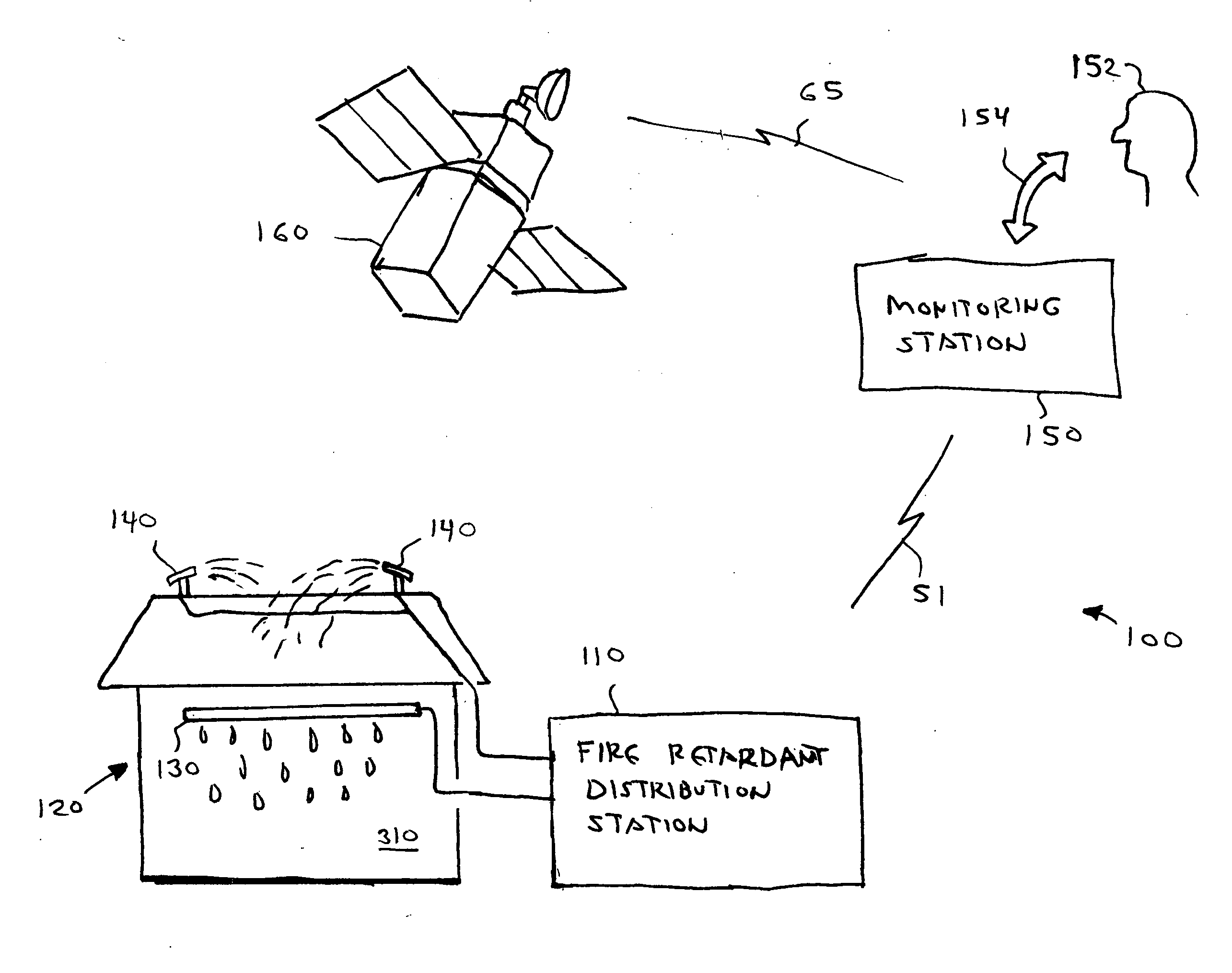
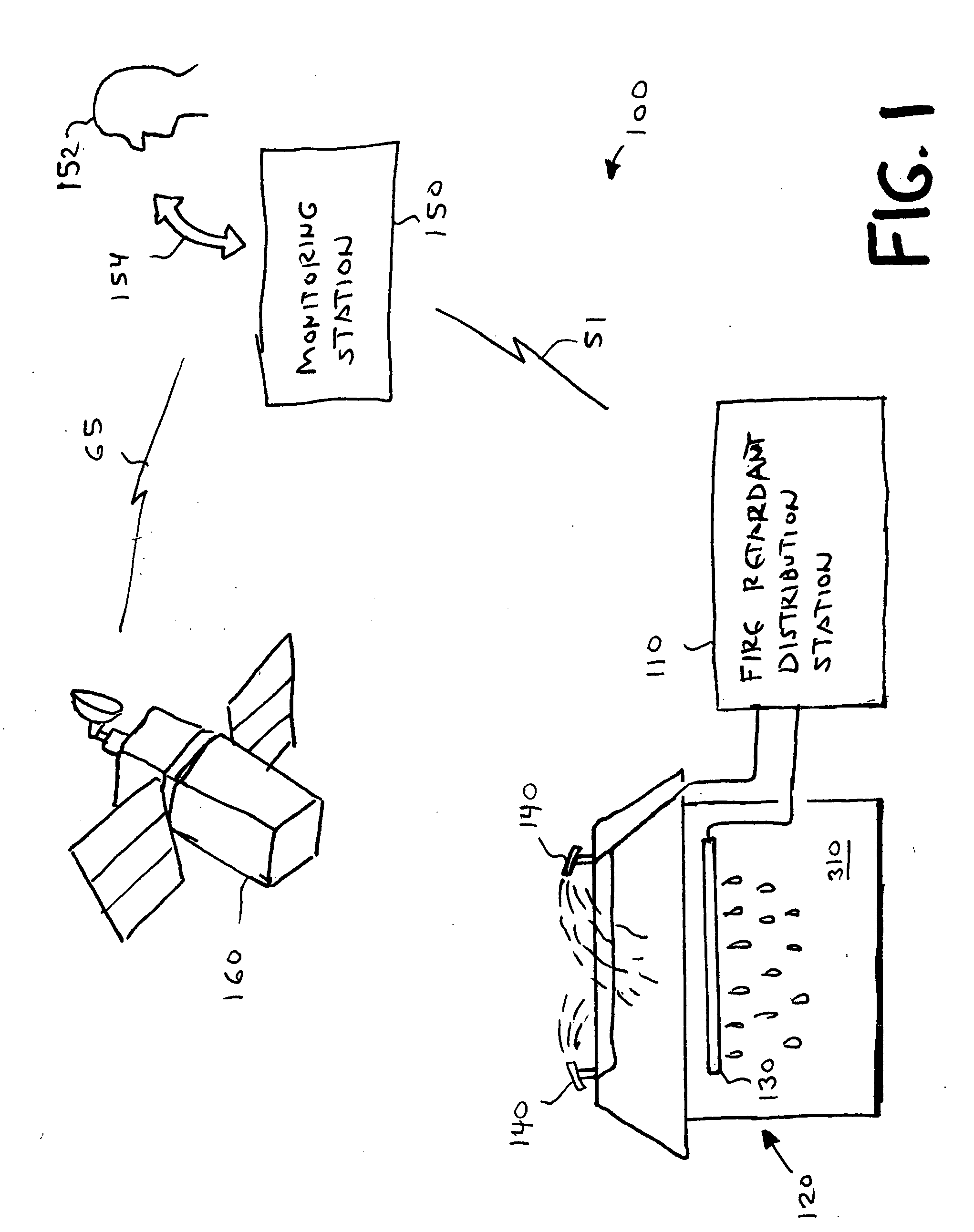
[0022] A fire prevention system according to various aspects of the invention provides numerous benefits, including efficient use of fire retardant when and where needed for effective protection of a structure. As may be better understood with reference to the simplified diagram of FIG. 1, exemplary fire prevention system 100 includes: a fire retardant distribution station 110; sprinklers 140; a porous pipe 130 attached to a building 120 being protected from fire; and a monitoring station 150 in communication with distribution station 110 via a wide-area connection 51. (FIG. 9 is a perspective view of structure 120 illustrating a cabinet 930 that houses various other components of distribution station 110 as discussed bel...


PUM


Abstract

A disclosed fire retardant application structure includes an elongated tube comprised of material that is water-porous throughout on one side of the tube and material that is water-impermeable on the remainder of the tube. A disclosed wildfire monitoring and service system includes a satellite-image monitoring computer that is programmed to display a composite map image defining locations of wildfires observed by satellite and multiple separate structures. The system also includes a wireless transmission subsystem that is capable of transmitting a signal from the central location to each of the structures selectively, and, at each of the structures, a fire-retardant application subsystem. Each of the application systems is directed at exterior surfaces of its respective structure and is responsive to a select signal that is transmitted through the transmission system. Variations and methods are also disclosed.

Description

CROSS REFERENCE TO RELATED APPLICATIONS [0001] This application claims benefit of U.S. Provisional Application No. 60 / 529,056 filed Dec. 12, 2003, which is incorporated herein by reference.BACKGROUND OF THE INVENTION [0002] Homes and other structures erected in wooded areas face a significant danger of being lost or severely damaged due to wildfires, especially when the surrounding woodlands are suffering from drought conditions. Such structures are frequently evacuated in the face of an approaching forest fire and thus are least protected by the opportunity for human intervention when the danger is greatest. In addition, vacation homes (which often represent a sizable proportion of the structures found in a given heavily forested area) are typically vacant during the week and thus are most likely to be unoccupied should a forest fire break out in the area, regardless of whether an evacuation is happening or not. [0003] It is well known to apply water or some other type of retardant...

Claims


Application Information

Patent Timeline
Patent Type & Authority Applications(United States)
IPC IPC(8): A62C3/02A62C35/00
CPCA62C3/0214A62C3/0292A62C3/0271
Inventor PALMER, GERALD R.MENDOZA, TIMOTHY P.METTLER, DAVID D.PAXON, JAMES E.ZUGMIER, GEORGE A.
Owner HYDROSHIELD L L C
Why Eureka
Try Eureka