
Brake dust cover structure of vehicle

a technology of brake dust cover and vehicle, which is applied in the direction of brake cooling, brake system, transportation and packaging, etc., can solve the problems of reducing deteriorating the braking function, increasing the impurities that enter along with the airflow, etc., to prevent impurities and improve the cooling efficiency of the brake disk.

Inactive Publication Date: 2005-06-16
HYUNDAI MOTOR CO LTD
View PDF10 Cites 24 Cited by
  • Summary
  • Abstract
  • Description
  • Claims
  • Application Information

AI Technical Summary

Benefits of technology

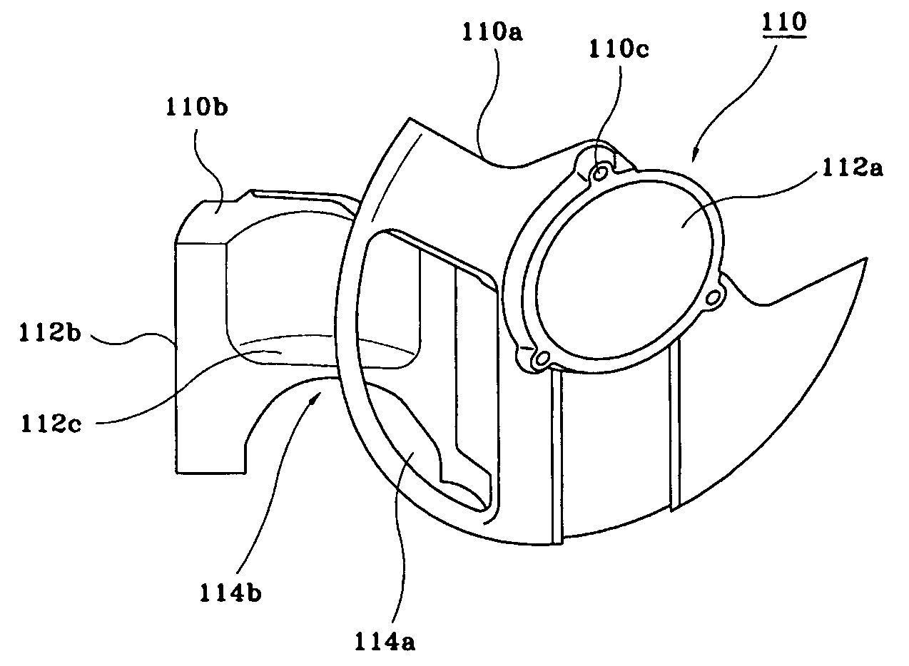
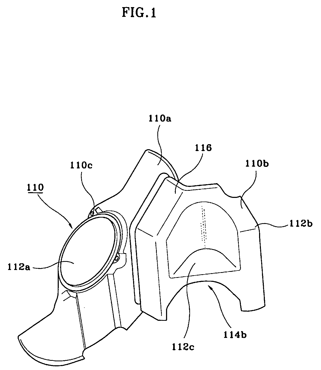
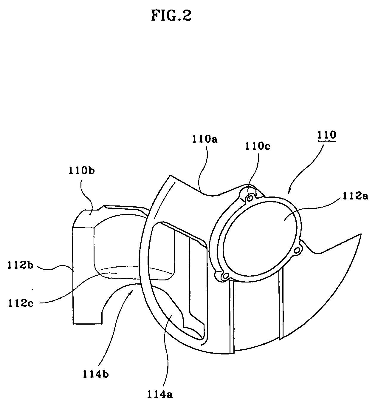
[0006] An embodiment of the present invention is provided to improve the cooling efficiency of a brake disk and to prevent impurities from entering into the brake disk. A brake dust cover of a vehicle comprises a cover plate having a partially cut-off configuration for enclosing a brake disk. The cover plate is formed with an air inlet toward the front of the vehicle and is fixed to a knuckle. A guide part protrudes out toward the front and inner side of the vehicle and is configured to guide air from the front of the vehicle to the air inlet.

Problems solved by technology

However, there is a drawback in the conventional brake system structure in that the brake dust cover wraps around most of the brake disk, deteriorating the heat emission of the brake disk due to the difficulty of air influx therein, and causing deterioration to the braking function by decreasing the cooling efficiency of the brake disk.
However, as the air influx increases in the above described structure, impurities that enter along with the air influx also increase.
This causes corrosion and abrasion in the brake disk, as well as unwanted noise.

Method used


Image

  • Brake dust cover structure of vehicle
  • Brake dust cover structure of vehicle
  • Brake dust cover structure of vehicle

Examples


Embodiment Construction

[0013] Referring to FIGS. 1 to 5, a brake dust cover 110 of a vehicle according to some embodiments of the present invention comprises a cover plate 110a and a guide part 110b. The cover plate 110a prevents nearby components from being thermally damaged by insulating the brake disk 120 from heat radiation. The cover plate 110a also prevents impurities (e.g., pieces of stone, soil or the like) from entering into the brake disk 120. The guide part 10b improves the cooling efficiency of the brake disk 120 by maximizing the amount of airflow into the brake disk 120.

[0014] The cover plate 110a has a partially cut-off configuration. The middle of the cover plate 110a is formed with a hole 112a therein. An air inlet 114a is formed at the cover plate 110a toward the frontal direction of the vehicle for providing air between the cover plate and brake disk. The upper portion of the air inlet 114a is configured to be inclined downwardly toward the center of the cover plate 110a. The cover pla...


PUM


Abstract

The brake dust cover structure of a vehicle prevents nearby components from being thermally damaged by insulating the brake disk from heat radiation and prevents impurities, such as pieces of stone, soil or the like, from entering into the brake disk along with air, thus preventing damage to the brake disk. The present invention further improves the cooling efficiency of the brake disk by maximizing the amount of airflow into the brake disk.

Description

CROSS-REFERENCE TO RELATED APPLICATIONS [0001] The present application is based on, and claims priority from, Korean Application Ser. No. 10-2003-0089527, filed on Dec. 10, 2003, the disclosure of which is hereby incorporated by reference herein in its entirety. FIELD OF THE INVENTION [0002] The present invention relates to a brake dust cover of a vehicle that is adapted to improve the cooling efficiency of a brake disk and to prevent impurities from entering into the brake disk. BACKGROUND OF THE INVENTION [0003] Generally, a brake dust cover enclosing a brake disk is installed to prevent impurities from entering into a brake system. The brake dust cover prevents impurities from entering into the brake disk when the impurities enter along with the airflow. Further, the brake dust cover prevents heat radiation generated from the brake disk affecting neighboring components, thereby preventing the components from being damaged by the impurities and heat. [0004] However, there is a dra...

Claims


Application Information

Patent Timeline
Patent Type & Authority Applications(United States)
IPC IPC(8): B60T5/00F16D65/00F16D55/00F16D55/02F16D65/847
CPCF16D2055/0037F16D55/00F16D65/847
Inventor LEE, BYUNG KYU
Owner HYUNDAI MOTOR CO LTD
Learn More