Formwork element of a round formwork

a formwork and element technology, applied in the field of formwork elements of round formwork, can solve the problems of complex structure and elaborate adjustment work of articulations

Inactive Publication Date: 2005-06-16
WD BETEILIGUNGS GMBH
View PDF18 Cites 5 Cited by
  • Summary
  • Abstract
  • Description
  • Claims
  • Application Information

AI Technical Summary

Benefits of technology

[0007] One important object of the invention is providing a formwork element of the above described type, which, at simple structuring can be employed for different radii of curvature of the round formwork without cutting the ends of the shaping bars or a replacement of these shaping bars being required.
[0014] The cast elements are preferably implemented in the form of plates, thus have the form of a flat rectangle in cross section. Such flat elements can most readily be contoured with the least deformation by means of rollers.

Problems solved by technology

Of disadvantage herein is the complicated structuring and the elaborate adjustment work of the articulations.

Method used


Image

  • Formwork element of a round formwork
  • Formwork element of a round formwork
  • Formwork element of a round formwork

Examples


Embodiment Construction

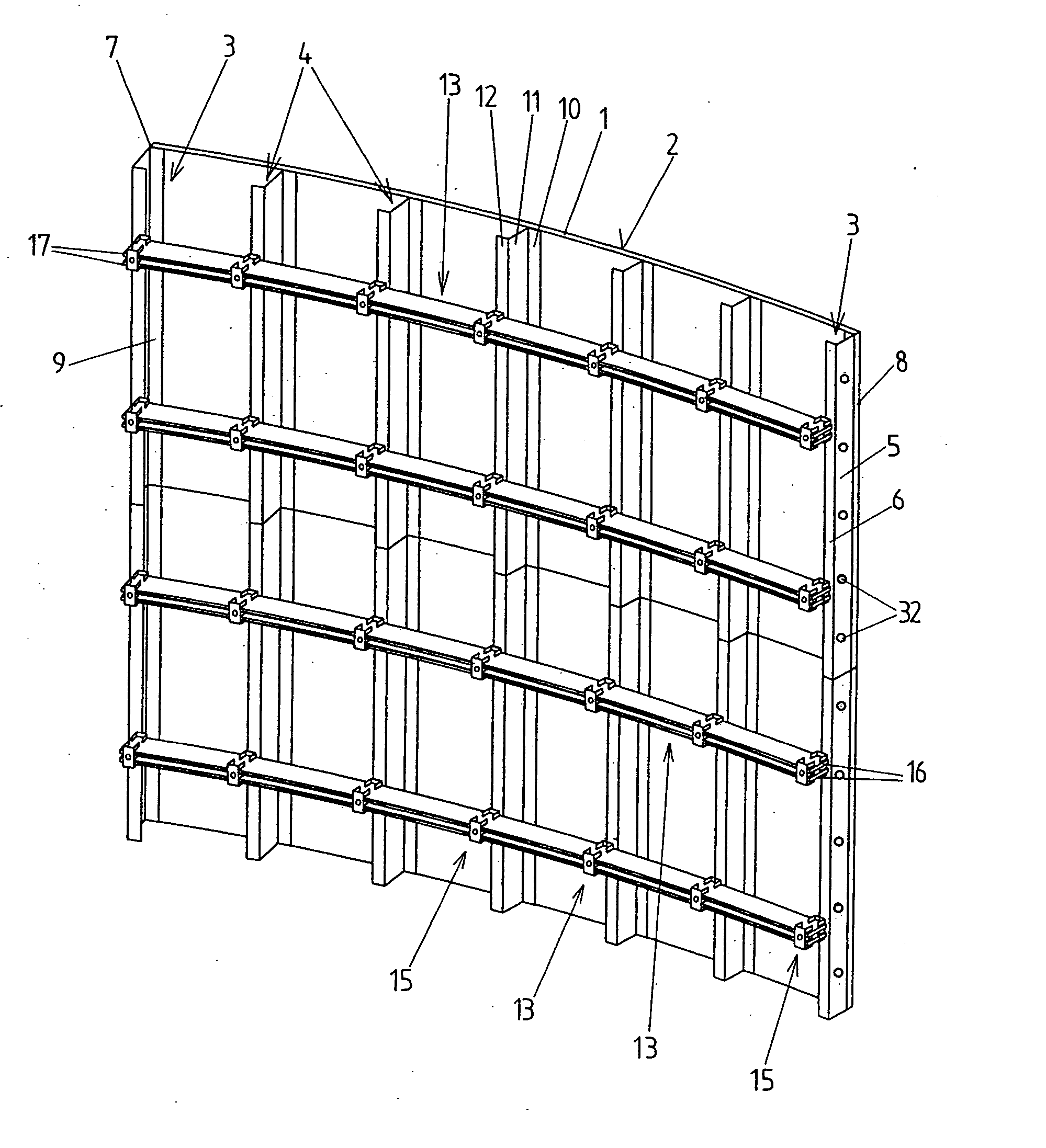
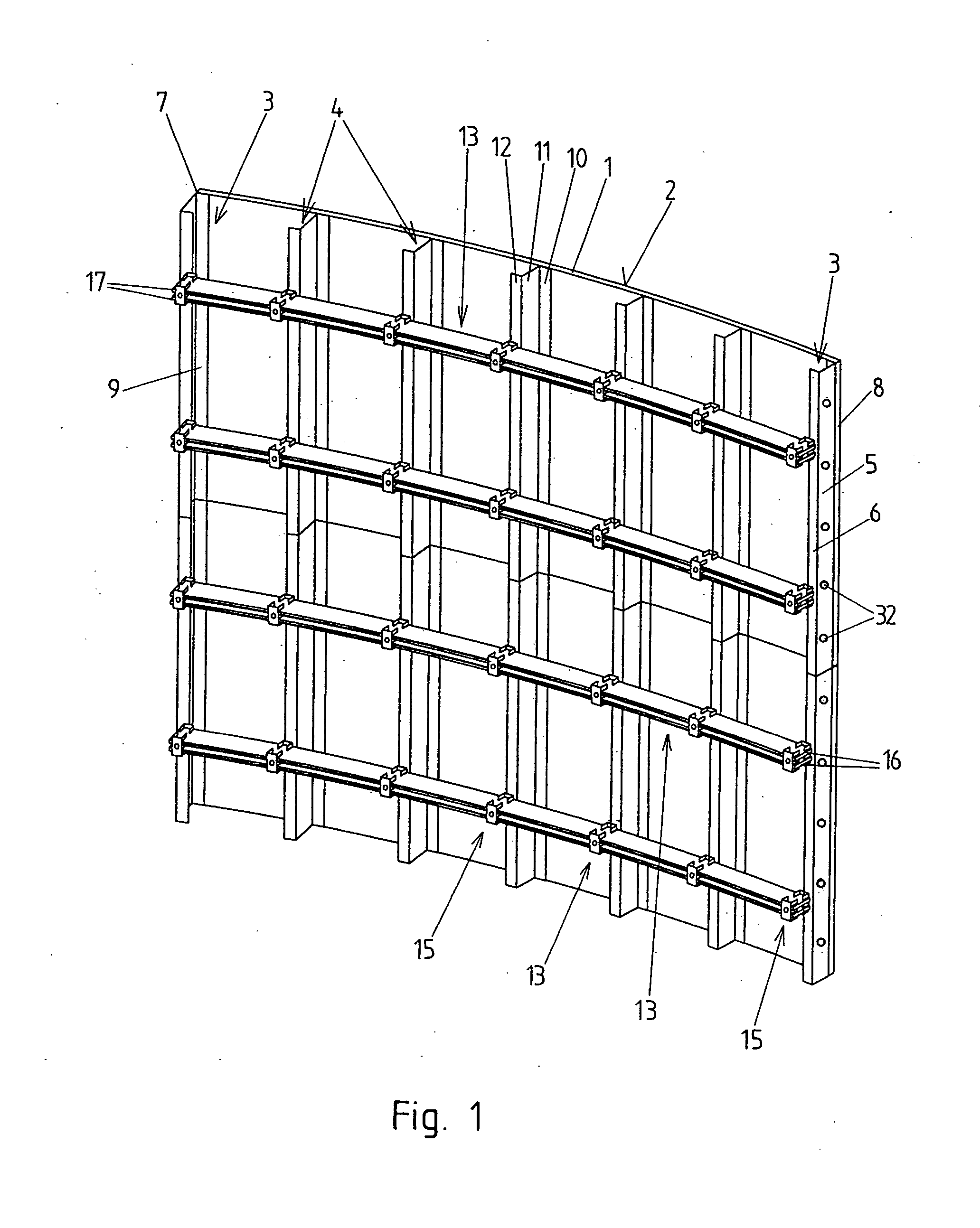
[0025] In FIG. 1 two formwork elements according to the invention of an inner formwork of a round formwork are disposed one above the other. The formwork elements of the outer formwork of the round formwork can be implemented in analogous manner. A particular formwork element comprises a form skin 1, which can be comprised for example of wood (for example laminated wood) and is implemented such that it is preferably continuous over the entire width of the formwork element. The form skin 1 can also be implemented to be continuous in height (dimension) or it can be comprised of several adjoining segments. The form skin 1 can, for example, also be formed by a steel plate.

[0026] On the backside of the form skin 1, facing away from the form surface 2, several vertically extending profile rails 3, 4 are disposed, e.g. bolted on. Herein two boundary-side profile rails 3 are available, which preferably have a U-form cross section. Each of the open sides of the U-form cross sections of the ...


PUM


Abstract

A formwork element of a round formwork comprises a form skin (1), on the backside of which vertically extending profile rails (3, 4) are disposed, with which horizontally extending curved shaping bars (13) are detachably connected. The shaping bars (13) are each formed by at least two, preferably at least four, cast elements (14), each of which extends over a large portion of the longitudinal extent of the shaping bar (13), and which are held together by shoes (15), and, due to a curvature-dependent offset (v) between the cast elements (14) in the longitudinal direction of the shaping bar (13) in each instance at least one, preferably at least two, of the cast elements (14) extend up to the particular front-side end (16, 17) of the shaping bar (13).

Description

BACKGROUND OF THE INVENTION [0001] a) Field of the Invention [0002] The invention relates to a formwork element of a round formwork comprising a form skin, on whose backside vertically extending profile rails are disposed, with which horizontal curved shaping bars are detachably connected. [0003] b) Description of Related Prior Art [0004] Formwork elements of this type are known. In order to implement one side of the round formwork (e.g. the outer formwork) from such formwork elements, several formwork elements of this type, to be arranged next to and / or above one another, are connected with one another. The outer and inner formwork can herein be developed analogously. In the region between the vertically extending profile sections, the concrete pressure is borne by the form skin. The shaping bars, also referred to as anchor rails, determine the curved shape of the formwork element. Further, these shaping bars conventionally form the bearing surface and abutment for the anchors of f...

Claims


Application Information

Patent Timeline
Patent Type & Authority Applications(United States)
IPC IPC(8): E04G11/04E04G11/06
CPCE04G11/065
Inventor MATHIS, HUGO
Owner WD BETEILIGUNGS GMBH
Why Eureka
Try Eureka