
Attachment system

a technology of attachment system and screw body, which is applied in the direction of fastening means, rod connections, pipes, etc., can solve the problems of press-fit nuts remaining in the support, inability to use conventional screw elements, and additional costs, so as to achieve the most economical production of counter-screws, facilitate the use of attachment systems, and the effect of favorable spring action

Inactive Publication Date: 2005-06-16
HILTI AG
View PDF8 Cites 33 Cited by
  • Summary
  • Abstract
  • Description
  • Claims
  • Application Information

AI Technical Summary

Benefits of technology

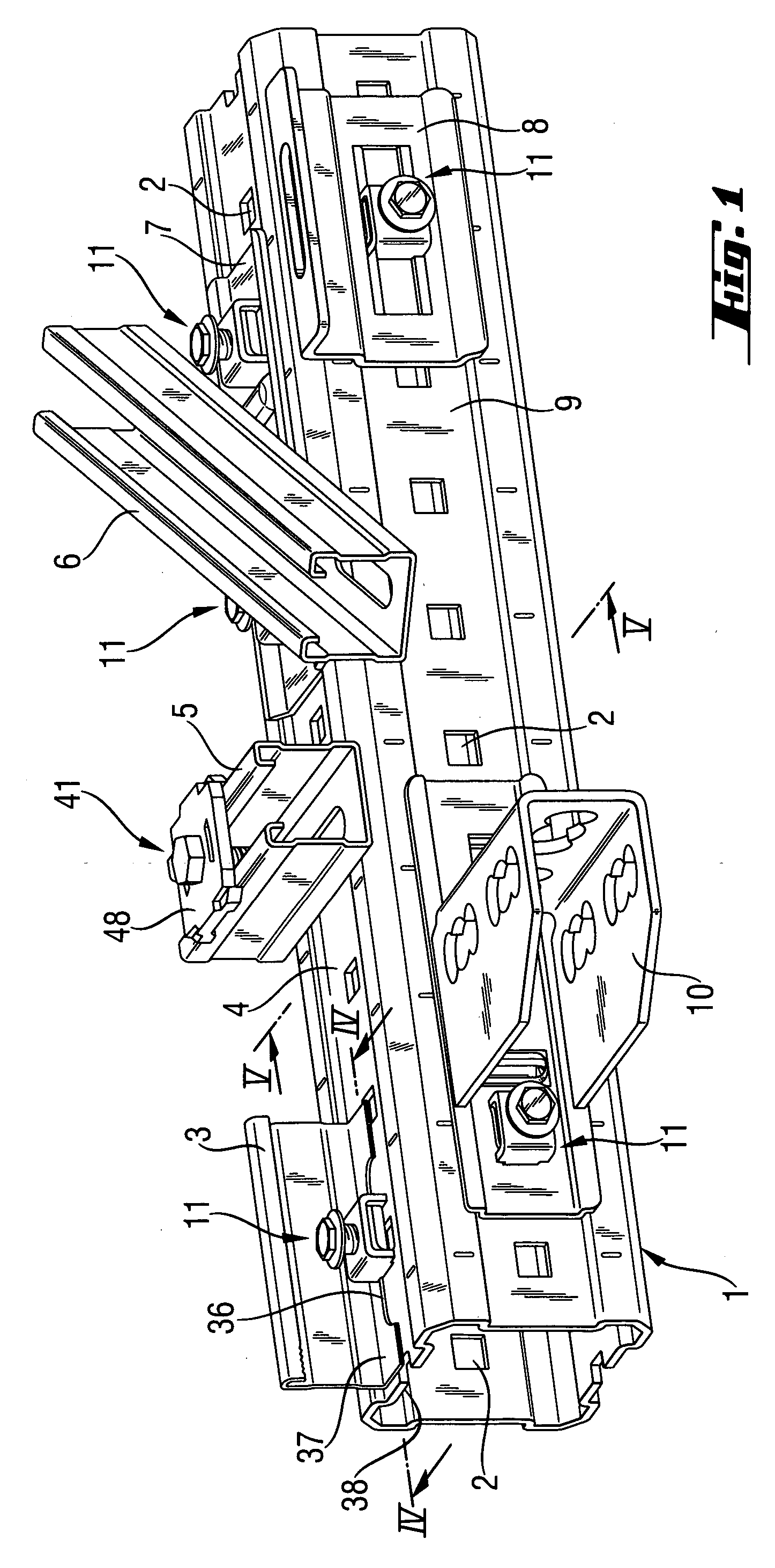
[0014] The first component has, at least in its elementary section that would lie on the second component, a through-opening which is formed, advantageously, as an elongate opening. The first component, which has several elementary sections, has through-openings in each of the elementary sections, which provides flexibility in the use of the second component. For mounting of the inventive attachment system, the first component is so aligned relative to the second component that the through-opening of the first component is arranged above an opening of the second component. The engagement section of the counters-screw means is introduced through both openings. Finally, the bearing member of the attachment system is properly arranged, and a screw element is inserted through the through-opening of the bearing member, and the first threaded section engages the second threaded section. The assembled attachment system is pushed sidewise until the connection section of the counter-screw means engages an edge of the opening in the second component. With suitable means, e.g., a wrench, which engages a hexagon screw head of the screw element that serves as torque transmitting means, the screw element is actuated, tightening the attachment system. Upon tightening, the counter-screw means is pulled in direction toward the bearing section which is supported on the first component, and the first component is secured to the second component, i.e., fixed thereon.
[0033] Advantageously, a guide sleeve is provided on the bearing section for the screw element. The guide sleeve guides the screw element such as a screw with an outer thread and a screw head, upon its displacement, which facilitates assembly of the attachment system. Advantageously, the second threaded section is formed in the guide sleeve. By increasing the thread length of the second threaded section, the counter-screw means can absorb large loads.

Problems solved by technology

A drawback of the above-described connection consists in that with a closed hollow profile or with a support accessible only from one side, the conventional screw elements cannot be used because retaining of the check nut is not possible.
The drawback of the use of a press-fit nut consists in that the openings in the supports should be adapted to the outer dimensions of the press-fit nut to prevent rotation of the nut in the support.
The insertion and press-fitting of the nut in a support lead to additional expenses associated with the assembly of a system which under certain side constraints such as, e.g., in height, and under unfavorable conditions at the assembly site, are not insignificant.
During disassembly or a change of the direction of a conduit or of the support structure, the press-fit nuts remain in the support which often is undesirable for constructive and / or aesthetic reasons.

Method used


Image

  • Attachment system
  • Attachment system
  • Attachment system

Examples


first embodiment

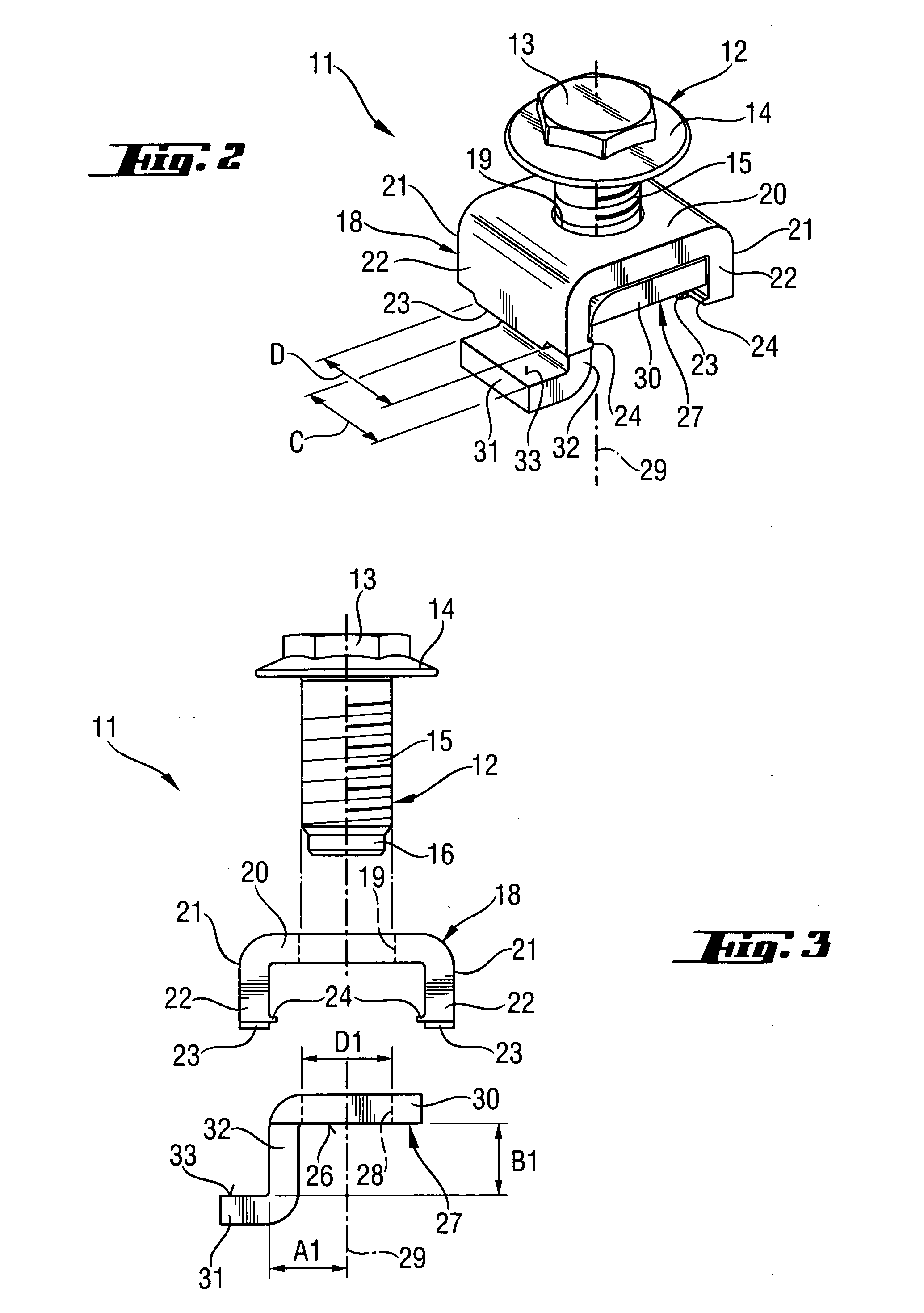
[0046]FIGS. 2 and 3 show the inventive attachment system represented by the attachment system 11. The attachment system 11 includes a screw element 12 the hexagon screw head of which forms torgue transmitting means 13. For operating the screw element 12, a wrench, which engages the hexagon screw head, is used. On the hexagon screw head, there is provided a band 14. The screw element 12 further has a threaded section 15 with an outer thread.

[0047] The attachment system 11 further includes a bearing member 18 having a through-opening 19 through which the screw element 12 is extendable and which is formed in a plate-shaped part 20. At the opposite ends of the plate-shaped part 20, there are provided, respectively, two webs 22 having each a projection 23.

[0048] The webs 22, together with the plate-shaped part 20, form the bridge-shaped bearing member 18. On the webs 22, there are provided, respectively, two locking noses 24 aligned opposite each other.

[0049] The attachment system 11 f...

second embodiment

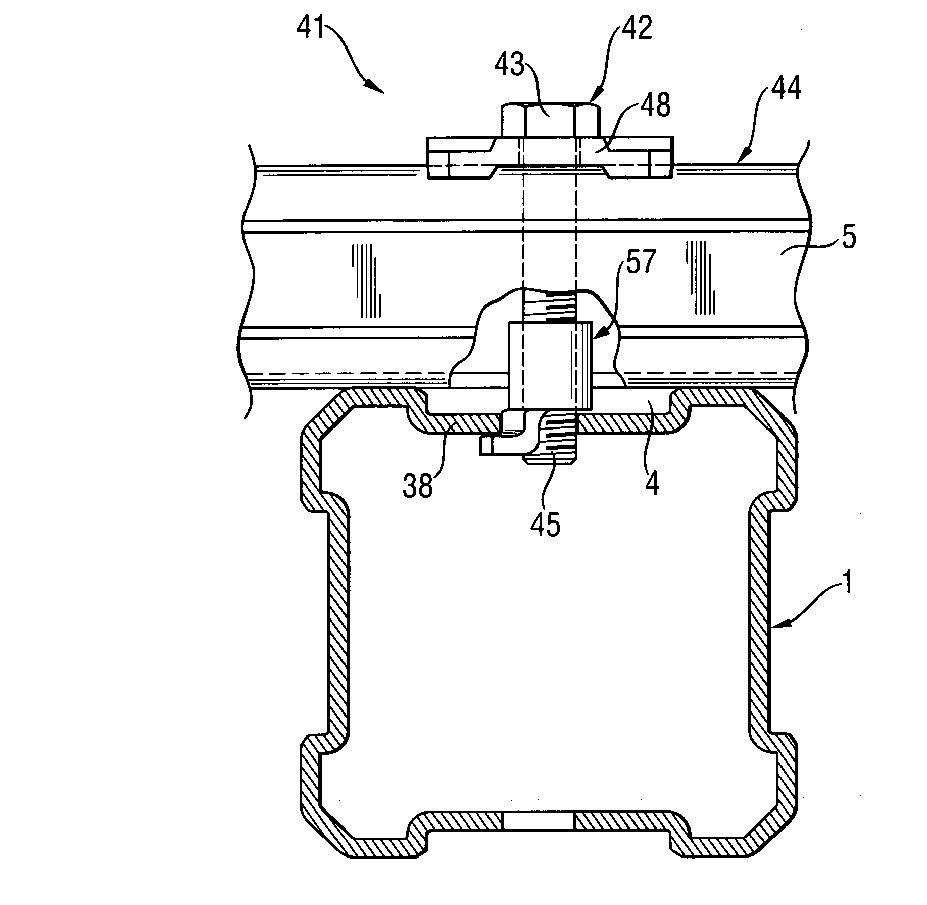
[0057]FIG. 5 shows an attachment system 41 according to the present invention. The attachment system 41 includes a screw that forms a screw element 42 and has a screw head 43, which forms the torque transmitting means, and a threaded section 45 with an outer thread. The attachment system 41 further includes a plate-shaped, rectangular bearing member 48 that abuts an open side 44 of the C-shaped mounting rail 5 and counter-screw means 57. The counter-screw means 57, which is shown in FIG. 6, has a bearing section 61, an engagement section 60, and a connection section 62 that connects the engagement section 60 with the bearing section 61. On the bearing section 61, there is provided a guide sleeve 63 having a height H for the screw element 42. The guide sleeve 63 has a threaded section 58 with an inner thread an defines an attachment axis 59.

[0058] Both the counter-screw means 27 and the counter-screw means 57 can be used as an independent element for a conventional attachment system....


PUM


Abstract

An attachment system for connecting a first component with a second component includes a screw element (12; 42) having at least regionwise, a first threaded section (15; 45), a bearing member (18; 48) for abutting one of the components and having a through-opening (19) through which the screw element (12; 42) is extendable; and a counter-screw element (27; 57; 77) defining an attachment axis (29; 59; 79) and having a second threaded section (28; 58; 78) cooperating with the first threaded section (15; 45), an engagement section (31; 61; 81), a bearing section (30; 60; 80) spaced from the engagement section (31; 61; 81) in a direction of the attachment axis (29; 59; 79), and a connection section (32; 62; 82) for connecting the bearing and engagement sections.

Description

BACKGROUND OF THE INVENTION [0001] 1. Field of Invention [0002] The present invention relates to an attachment system for connecting a first component with a second component and including a screw element having torgue transmitting means and, at least regionwise, a first threaded section, a bearing member for abutting one of the components and having a through-opening through which the screw element is extendable, and counter-screw means defining an attachment axis and having a second threaded section cooperating with the first threaded section of the screw element. The present invention also relates to counter-screw means for an attachment system. [0003] 2. Description of the Prior Art [0004] In construction of conduits and in particular of industrial pipelines, steel constructions are formed of steel constructional components which form a skeleton-like framework for the conduits. Conventionally, supports of a mounting system and having, e.g., a closed hollow cross-section and stan...

Claims


Application Information

Patent Timeline
IPC IPC(8): F16B7/18F16B37/02F16B37/04
CPCF16B7/187Y10T403/4674F16B37/044F16B37/02F16B2200/40
Inventor HOFFMANN, ARMIN
Owner HILTI AG
Learn More