Horizontal rotary compressor

a compressor and horizontal technology, applied in the direction of machines/engines, liquid fuel engines, lighting and heating apparatus, etc., can solve the problems of low reliability and insufficient oil feed to the individual sliding portions, and achieve the effect of high reliability

Inactive Publication Date: 2005-06-16
TOSHIBA CARRIER CORP
View PDF10 Cites 22 Cited by
  • Summary
  • Abstract
  • Description
  • Claims
  • Application Information

AI Technical Summary

Benefits of technology

[0012] An object of the present invention is to provide a horizontal rotary compressor that ensures oil feed to

Problems solved by technology

However, according to the lubrication structure described above, when the oil level in an oil draw-in portion falls in the event of, for example, operation of the compressor in a tilted state, sufficient drawing-in cannot be achieved, thereby c

Method used


Image

  • Horizontal rotary compressor
  • Horizontal rotary compressor
  • Horizontal rotary compressor

Examples


Embodiment Construction

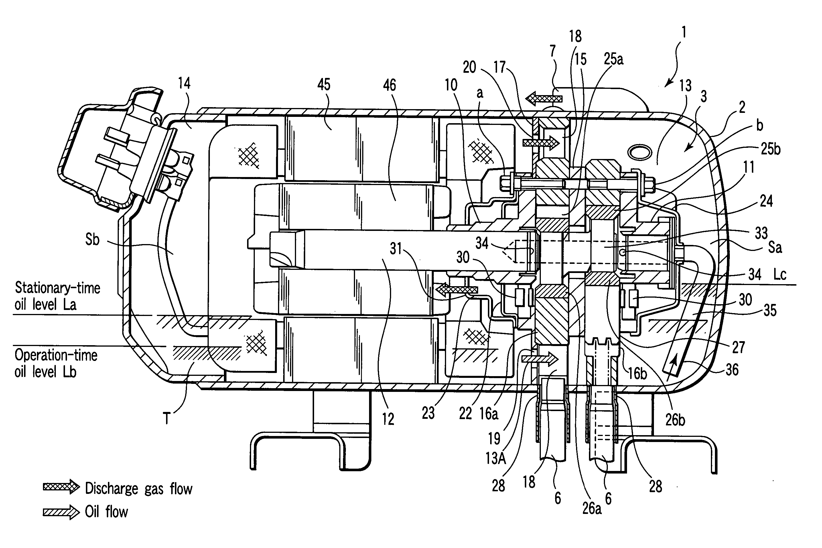
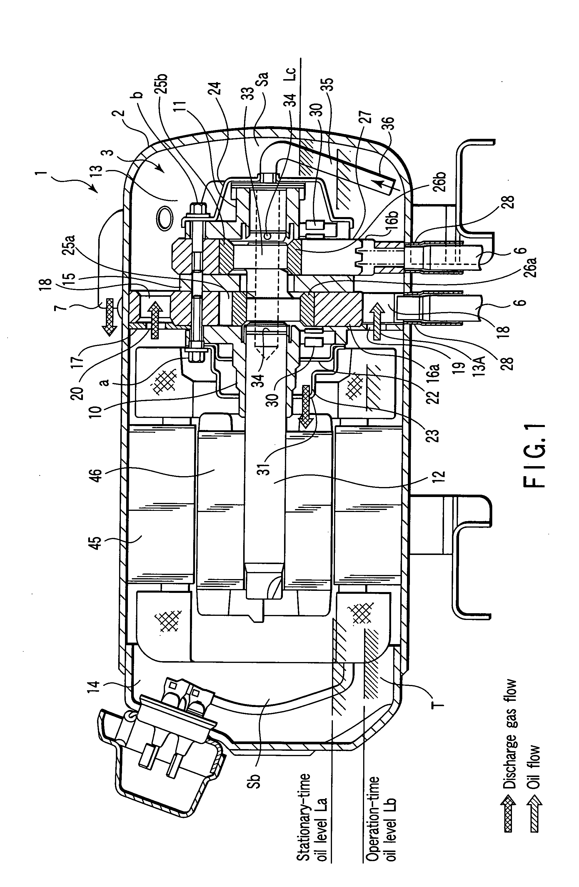
[0020]FIG. 1 is a cross-sectional front view of a horizontal rotary compressor; and FIG. 2 is a cross-sectional side view of the compressor.

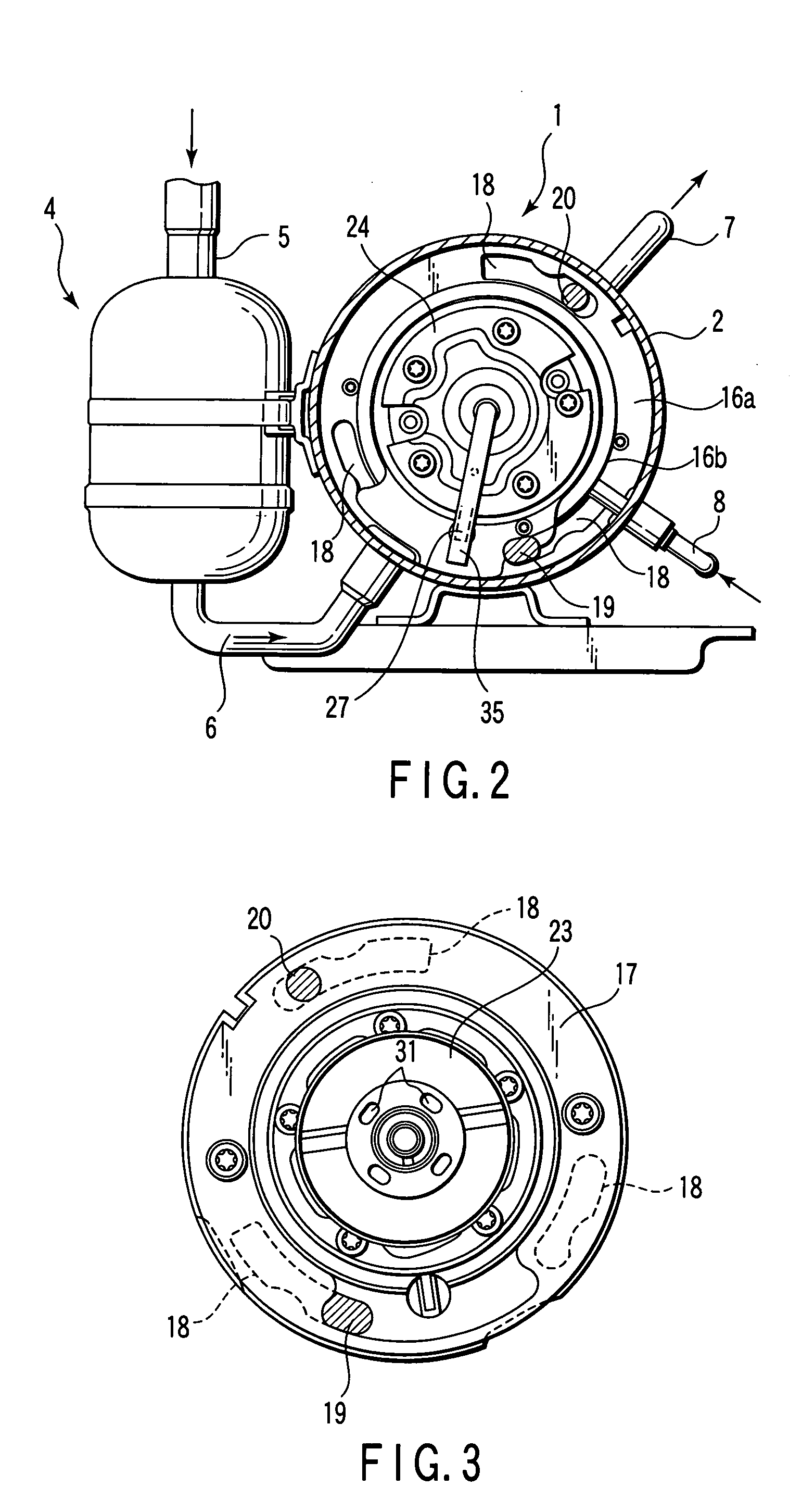
[0021] In the drawing, 1 denotes the horizontal rotary compressor configured such that an electrically powered compressor body 3 is accommodated in a hermetic receptacle 2 as described hereinafter. In the drawing figure, 4 denotes an accumulator, an upper end portion of which is connected to refrigerant tubing 5 that communicates with an evaporator (not shown) that serves to constitute a refrigeration cycle.

[0022] An lower end portion of the accumulator 4 and a lower portion of the hermetic receptacle 2 of the horizontal rotary compressor 1 are coupled by means of suction tubing 6 in communication with each other. There is provided a two-cylinder type compressor mechanism portion, wherein two pieces of suction tubing 6 are connected in an overlapped state, as shown in FIG. 2.

[0023] Discharge refrigerant tubing 7 is connected in a position sym...


PUM


Abstract

A horizontal rotary compressor is configured such that an electrically powered compressor body is accommodated in a horizontally long hermetic receptacle in which a lubricating oil is accumulatively preserved, an interior of the hermetic receptacle is partitioned by a partition member into an oil storage portion space in which the compressor mechanism portion is positioned and an electric motor side space in which the electric motor portion is positioned, an oil communication portion is provided below the partition member, a gas communication opening is provided in an upper portion of the partition member, and an oil feed passageway is formed of a center opening, an oil guide opening, and oil suction tubing along the rotation axis.

Description

CROSS REFERENCE TO RELATED APPLICATIONS [0001] This is a Continuation Application of PCT Application No. PCT / JP03 / 09205, filed Jul. 18, 2003, which was published under PCT Article 21(2) in Japanese. [0002] This application is based upon and claims the benefit of priority from prior Japanese Patent Application No. 2002-220247, filed Jul. 29, 2002, the entire contents of which are incorporated herein by reference.BACKGROUND OF THE INVENTION [0003] 1. Field of the Invention [0004] The present invention relates to a horizontal rotary compressor that serves to constitute a refrigeration cycle of any one of, for example, refrigerating units and air-conditioning units. [0005] 2. Description of the Related Art [0006] While various types of compressors are used with, for example, refrigerating units and air-conditioning units, among those being popularly used are rotary compressors that have high reliability and produce low operating noise. [0007] Among those mostly accounting for regular ty...

Claims


Application Information

Patent Timeline
IPC IPC(8): F01C21/10F04C18/356F04C23/00F04C29/02
CPCF01C21/104F01C21/108F04C29/025F04C23/008F04C29/023F04C18/3564
Inventor HASEGAWA, MASUMIAOKI, TOSHIMASAGOTOU, SHINYA
Owner TOSHIBA CARRIER CORP
Why Eureka
Try Eureka