Fuel cell system

a fuel cell and system technology, applied in the field of fuel cell systems, can solve problems such as complex structur

Inactive Publication Date: 2005-06-16
NISSAN MOTOR CO LTD
View PDF9 Cites 15 Cited by
  • Summary
  • Abstract
  • Description
  • Claims
  • Application Information

AI Technical Summary

Benefits of technology

[0006] Therefore, the present invention has an object to be able to comply with an increase in a hydrogen inlet port rate without causing a complexity in structure.

Problems solved by technology

Further, simply, mere provision of three ejectors causes complexity in structure because of a need for the switch-over mechanisms and the back flow protection mechanisms.

Method used


Image

  • Fuel cell system
  • Fuel cell system
  • Fuel cell system

Examples


first embodiment

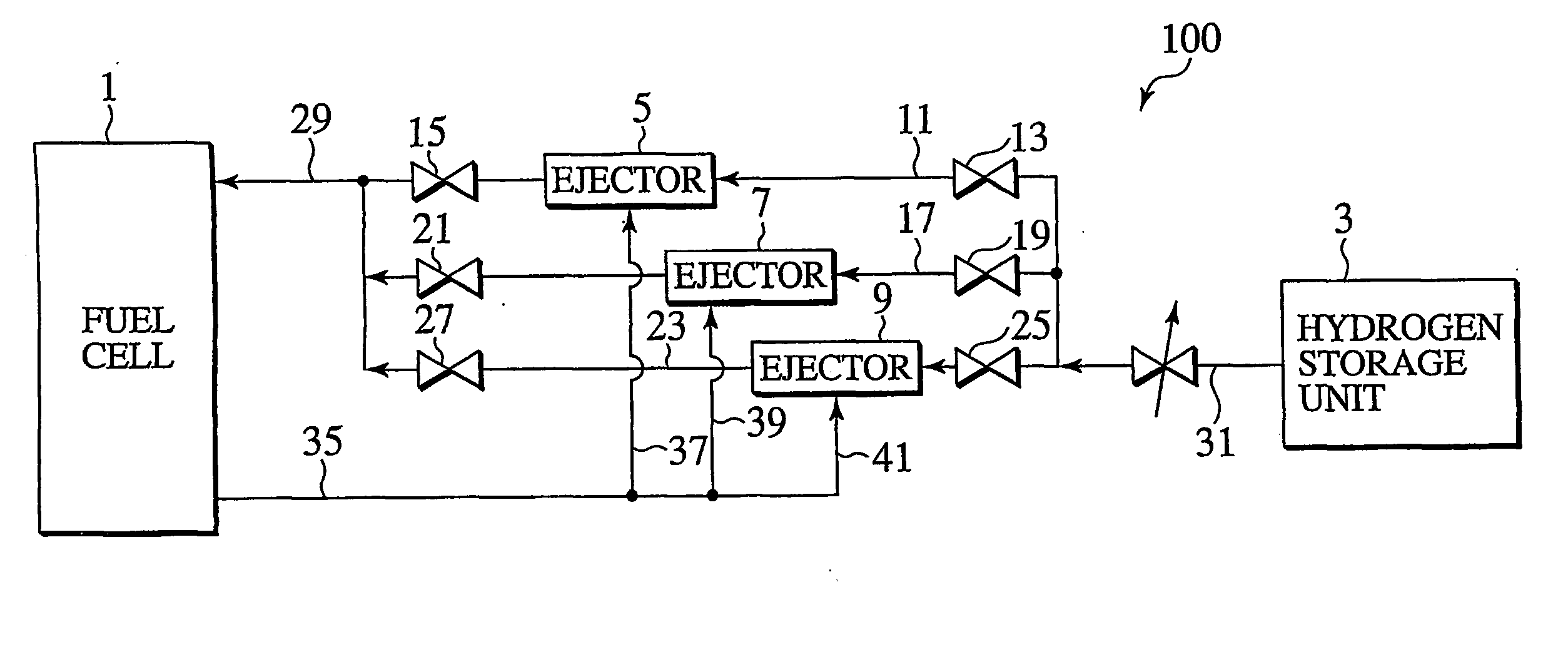
[0021]FIG. 1 is an overall structural view of a fuel cell system of a first embodiment according to the present invention. The fuel cell system 100 is comprised of a fuel cell 1 and a hydrogen storage unit 3, serving as a hydrogen supply source, between which three ejectors 5, 7, 9 are connected in parallel to allow hydrogen in excess thereof, supplied to the fuel cell 1, to be recirculated to the fuel cell 1.

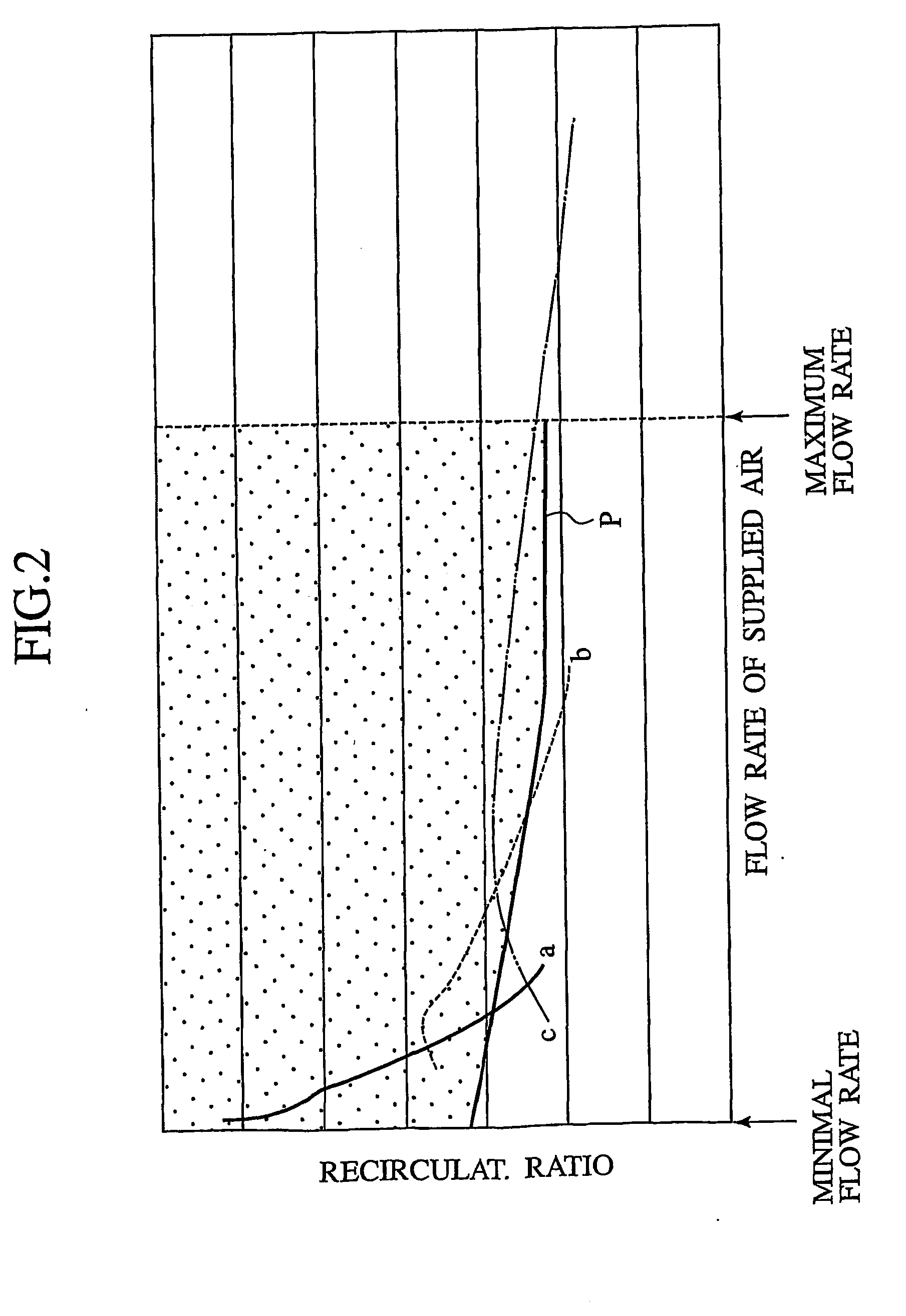
[0022] As shown in FIG. 2, the ejectors 5, 7, 9 are so configured as to have relationships, different from one another, in terms of a flow rate of air (with hydrogen being referred to in the presently filed embodiment) to be supplied and a recirculation ratio (ratio of a volume in terms of the flow rate to be supplied). Here, a solid line a corresponds to the ejector 5, a broken line b corresponds to the ejector 5 and a single dot line c corresponds to the ejector 5, with these ejectors being used in combination to obtain a widened range of the flow rate of air to be supplied (...

second embodiment

[0030]FIG. 3A is a cross sectional view of an ejector unit 50 equipped with three ejector sections for use in a fuel cell system of the present invention. The ejector unit 50 includes a housing 43 of a cubic structure formed with a valve body receiver cavity 45 in which a cylindrical valve body 47 is disposed for sliding movement along a vertically extending axis CL1 in the figure.

[0031] Formed in the housing 43 at left and right symmetric positions thereof in a substantially center area along a vertical direction are a hydrogen inlet port 49 and a hydrogen outlet port 51 which are open to the valve body receiver cavity 45. Hydrogen supplied from the hydrogen storage unit, that is not shown, enters the hydrogen inlet port 49 and is discharged from the hydrogen outlet port 51 to be supplied to the fuel cell that is not shown. Also, formed at a lower portion of the housing 43 is a hydrogen recirculation port 53 which communicates with the valve body receiver cavity 45. Excess hydrogen...

third embodiment

[0048]FIG. 5A is a cross sectional view of an ejector unit 50A equipped with three ejector sections for use in a fuel cell system of the present invention. FIG. 5B is a cross sectional view taken on line 5B-5B of FIG. 5A. This ejector unit includes a housing 85 formed in a substantially cubic configuration and having a valve body receiver cavity 87 in which a cylindrical valve body 89 is disposed for rotational movement about a center of a vertically extending axis CL2 in FIG. 5A.

[0049] Formed in the housing 85 at left and right symmetric positions thereof in a substantially central area along a vertical direction are a hydrogen inlet port 91 and a hydrogen outlet port 93 which are open to the valve body receiver cavity 87. Hydrogen supplied from the hydrogen storage unit, that is not shown, enters the hydrogen inlet port 91 and is discharged from the hydrogen outlet port 93 and supplied to the fuel cell that is not shown. Also, formed in the housing 85 at a lower portion thereof is...


PUM

PropertyMeasurementUnit
flow rateaaaaaaaaaa
structureaaaaaaaaaa
pressureaaaaaaaaaa

Abstract

Three ejectors 5, 7, 9 with differences in specification are connected in parallel between a hydrogen storage unit 3 and a fuel cell 1. Respective ejectors 5, 7, 9 allow excess hydrogen, discharged from the fuel cell 1, to pass through a hydrogen recirculating common flow passage 35 and to be recirculated through three recirculation branch flow passages 37, 39, 41. Shut-off mechanisms 13, 15, 19, 21, 25, 27 are disposed at both upstream and downstream sides of the respective ejectors 5, 7, 9, with closing and opening of the shut-off mechanisms located at both the upstream and downstream sides of the respective ejectors 5, 7, 9 permitting the three ejectors 5, 7, 9 to be properly used.

Description

TECHNICAL FIELD [0001] This invention relates to a fuel cell system equipped with ejectors adapted to an excess component, expelled from a fuel cell, of hydrogen supplied to the fuel cell from a hydrogen supply source to be recirculated to the fuel cell. BACKGROUND ART [0002] With respect to a flow rate of hydrogen to be supplied to a fuel cell, there are many probabilities where a hydrogen stoichiometric ratio (an amount of hydrogen to be introduced / an amount of hydrogen consumed for electric power generation) is ensured to lie at a value greater than 1 (for instance, 1.5), with hydrogen resulting from non-use in reaction being recirculated for the purpose of improving a coefficient of utilization of hydrogen. [0003] When in use of ejectors for such recirculation, although there is a case where a single ejector is suffice, another case exists where two ejectors are switched over and selected for use depending upon the flow rate. But, when using the two ejectors to be switched over,...

Claims


Application Information

Patent Timeline
Patent Type & Authority Applications(United States)
IPC IPC(8): F04F5/46F04F5/54H01M2/08H01M8/00H01M8/02H01M8/04
CPCF04F5/461F04F5/466Y02E60/50H01M8/04097H01M8/04223F04F5/54H01M8/04228H01M8/04303Y10T137/2564Y10T137/2572F04F5/46H01M8/04
Inventor UOZUMI, TETSUO
Owner NISSAN MOTOR CO LTD
Why Eureka
Try Eureka