Premixed air-fuel mixture supply device

a technology of air-fuel mixture and supply device, which is applied in the direction of lighting and heating apparatus, combustion types, and combustion using lumps and pulverizing fuel, etc., can solve the problems of satisfactorily vaporizing, and achieve the effect of improving fuel atomizing characteristic, high injecting rate and high injecting velocity

Active Publication Date: 2005-06-16
KAWASAKI HEAVY IND LTD
View PDF7 Cites 21 Cited by
  • Summary
  • Abstract
  • Description
  • Claims
  • Application Information

AI Technical Summary

Benefits of technology

[0024] The effect of injecting main fuel radially outward will be explained. Main fuel is injected perpendicularly or substantially perpendicularly to the air currents flowing through the combustion air passage from the intermediate wall into the outer combustion air passage. While the combustor associated with the premixed air-fuel mixture supply device is in a high-load operation, fuel is injected at a high injecting rate and a high injecting velocity through the fuel injecting holes. Consequently, the injected fuel impinges on the atomization lip, flows in a liquid film along the surface of the atomization lip, and is atomized satisfactorily at the edge of the atomization lip by air currents to produce a lean air-fuel mixture.
[0025] While the combustor is in a low-load operation, fuel is injected at a low injecting rate and a low injecting velocity through the fuel injecting holes. Consequently, most part of the injected fuel flows in a liquid film along the surface of the intermediate wall, and the outer surface of the atomization lip is atomized at the edge of the atomization lip by air currents flowing along the outer and the inner surface of the atomization lip, and the atomized fuel is vaporized and mixed with air to produce a lean premixed air-fuel mixture. Since the combustion air passage is divided into the outer and the inner air passages, and the atomization lip is extended in the combustion air passage, the liquid film can be atomized by air currents flowing along the outer and the inner surface of the atomization lip to provide the premixed air-fuel mixture supply device with an improved fuel-atomizing characteristic. The same effect can be exercised by injecting main fuel radially inward.
[0026] Fuel can be injected without increasing the fuel feed pressure when the combustor is in a high-load operation, and a large fuel feed system is not necessary. Since there is no need to reduce the number of the fuel injecting holes, fuel and combustion air can be satisfactorily mixed. And since there is no need to reduce the diameter of the fuel holes, the fuel holes will not be closed by caulking.

Problems solved by technology

A fuel injector included in combustor for a gas turbine or an aircraft engine operates according to load on the combustor that varies in a wide load range Therefore, in most cases where the combustor is in a low-load operation requiring fuel injection at a low rate, fuel injected by the fuel injector is unable to flow across air currents to or near to a wall surrounding the fuel injection valve and unable to vaporize satisfactorily.

Method used


Image

  • Premixed air-fuel mixture supply device
  • Premixed air-fuel mixture supply device
  • Premixed air-fuel mixture supply device

Examples


first embodiment

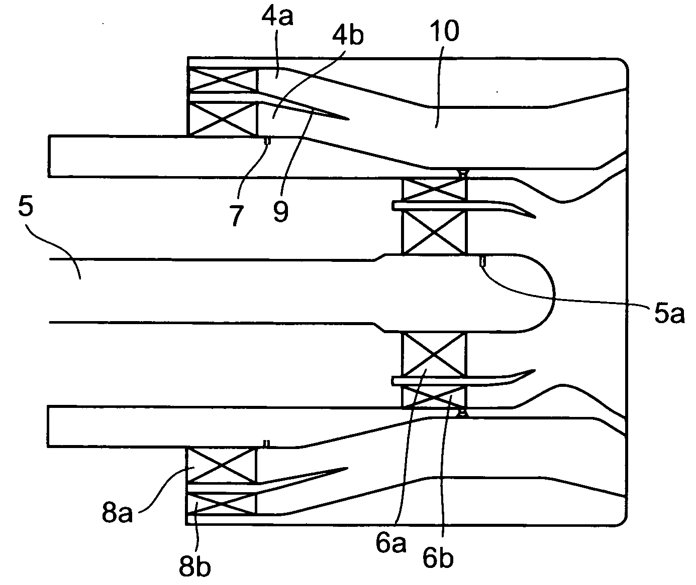
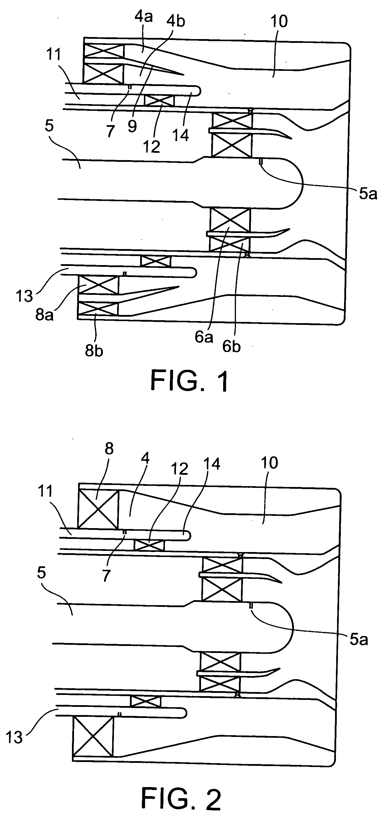
[0035] Referring to FIG. 1 showing a premixed air-fuel mixture supply device in a first embodiment according to the present invention that injects fuel radially outward, an inner wall is joined to the head of a combustor liner (combustor liner 2 shown in FIG. 5) and an outer wall is joined to the head of the combustor liner so as to surround the inner wall. A pilot fuel injection unit is formed inside the inner wall, and a main fuel injection unit is formed in a space defined by the inner and the outer wall. The main fuel injection unit has a prevaporizing, premixing chamber 10 and is provided with swirling devices and an atomization lip dividing an upstream part of the prevaporizing, premixing chamber 10 into an outer combustion air passage 4a and an inner combustion air passage 4b. An intermediate wall 13 is inserted in the inner combustion air passage 4b to define a secondary combustion air passage 11 around the inner wall. The intermediate wall 13 has a tail part shaped in an at...

third embodiment

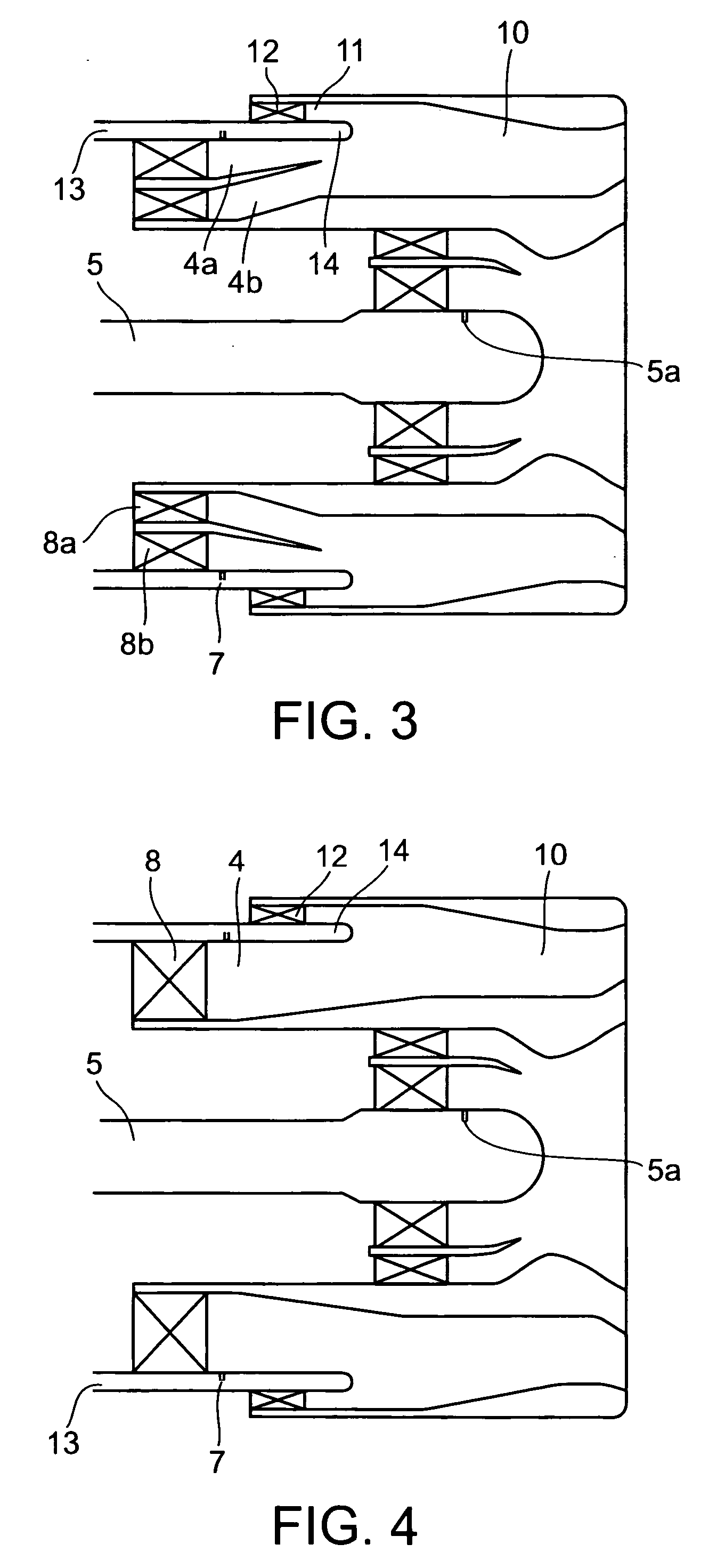
[0037]FIG. 3 shows a premixed air-fuel mixture supply device in a third embodiment according to the present invention that injects fuel radially inward. Referring to FIG. 3, an inner wall is joined to the head of a combustor liner (combustor liner 2 shown in FIG. 5) and an outer wall is joined to the head of the combustor liner so as to surround the inner wall. A pilot fuel injection unit is formed inside the inner wall, and a main fuel injection unit is formed in a space defined by the inner and the outer wall. The main fuel injection unit has a prevaporizing, premixing chamber 10 and is provided with swirling devices and an atomization lip dividing an upstream part of the prevaporizing, premixing chamber 10 into an outer combustion air passage 4a and an inner combustion air passage 4b. An intermediate wall 13 is inserted in the outer combustion air passage 4a to define a secondary combustion air passage 11 around the inner wall. The intermediate wall 13 has a tail part shaped in a...


PUM


Abstract

A premixed air-fuel mixture supply device is joined to a combustor liner included in a combustor for a gas turbine or an aircraft engine. The premixed air-fuel mixture supply device has a pilot fuel injection unit having an inner wall, and a prevaporizing, premixing main fuel injection unit having an outer wall surrounding the inner wall. A combustion air passage is defined by the inner and the outer wall. An intermediate wall is disposed in the combustion air passage so as to divide an upstream part of the combustion air passage into a secondary combustion air passage surrounding the inner wall, and an outer combustion air passage surrounding the intermediate wall. Fuel inject holes are formed in the intermediate wall to inject fuel radially outward into the outer combustion air passage. A swirling device is disposed in the secondary combustion air passage to swirl combustion air flowing through the secondary combustion air passage. An atomization lip is formed in a tail part of the intermediate wall.

Description

BACKGROUND OF THE INVENTION [0001] 1. Field of the Invention [0002] The present invention relates to a premixed air-fuel mixture supply device for supplying a premixed air-fuel mixture to a combustor for a gas turbine or an aircraft engine and, more particularly, to a premixed air-fuel mixture supply device capable of atomizing fuel satisfactorily while the associated combustor is in a low-load operation. [0003] 2. Description of the Related Art [0004] A conventional combustor for a gas turbine or an aircraft engine has a combustor casing, and a cylindrical or annular combustor liner disposed in the combustor casing to define a combustion chamber. A fuel nozzle is connected to a head part of the combustor liner. The combustor casing and the combustor liner define an air passage through which air supplied by an air compressor flows into the combustion chamber. [0005] When fuel is injected in air for diffusive combustion in the combustion chamber of this combustor of a gas turbine or ...

Claims


Application Information

Patent Timeline
Patent Type & Authority Applications(United States)
IPC IPC(8): F23R3/30F02C7/232F23R3/10F23R3/14F23R3/28F23R3/34
CPCF23R3/286F23R3/14
Inventor ODA, TAKEONINOMIYA, HIROYUKIKOBAYASHI, MASAYOSHI
Owner KAWASAKI HEAVY IND LTD
Why Eureka
Try Eureka