Fuel pump arrangements

a technology of fuel pump and arrangement, which is applied in the direction of piston pump, positive displacement liquid engine, electric control, etc., can solve the problems of noise, vibration and wear associated with the operation of the pump, and achieve the effects of reducing noise and vibration, and ensuring the effect of pump operation

Inactive Publication Date: 2015-08-13
DELPHI TECH IP LTD
View PDF11 Cites 5 Cited by
  • Summary
  • Abstract
  • Description
  • Claims
  • Application Information

AI Technical Summary

Benefits of technology

[0016]Because the fuel volume displaced in the first and second pumping strokes differs, the pump arrangement can be operated in a more efficient way than prior art arrangements in which each of the pumps has the same fuel volume displacement per pumping stroke. The present invention allows a choice of either a small or a large volume of fuel to be pumped over a whole pumping stroke, therefore allowing greater control of the rail pressure whilst reducing noise and vibration and maintaining a high pumping efficiency.
[0017]In particular, at low injection rates, when the demand for high-pressure fuel is relatively low, fuel can be delivered from the pump arrangement using only the smaller-volume, second pumping stroke. In this way, only the fuel required for delivery is pressurised, and the wastage of pressurised fuel can be avoided. Furthermore, noise and vibration is minimised. At higher injection rates, when the demand for high-pressure fuel is relatively high, fuel can be delivered using the larger-volume, first pumping stroke. In general, fuel can be delivered from part or all of the first pumping stroke and / or part or all of the second pumping stroke to optimise the efficiency of the pump arrangement, and also to optimise the variation in the pressure of fuel output by the pump arrangement.

Problems solved by technology

The noise, vibration and wear associated with operation of the pump 10 also increase.

Method used


Image

  • Fuel pump arrangements
  • Fuel pump arrangements
  • Fuel pump arrangements

Examples


first embodiment

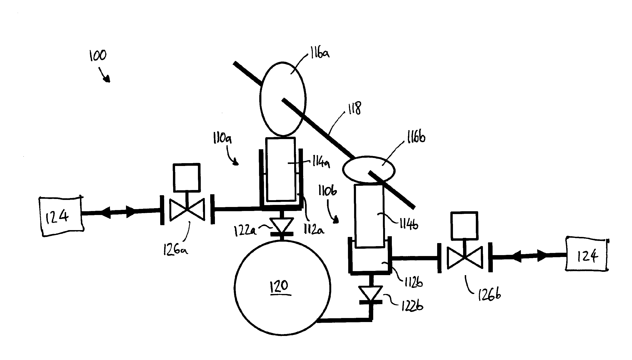
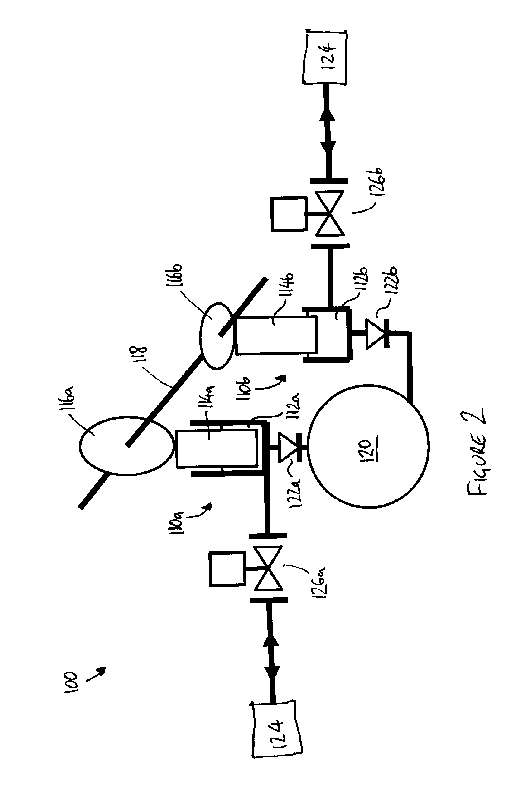
[0038]FIG. 2 shows part of a fuel injection system 100 having a fuel pump arrangement according to the present invention. The fuel pump arrangement includes a plurality of fuel pumps of the unit pump type. In the illustrated embodiment, first and second fuel pump units 110a, 110b are provided.

[0039]Each fuel pump unit 110a, 110b, referred to hereafter as a fuel pump, comprises a pumping chamber 112a, 112b and a pumping element or plunger 114a, 114b arranged for reciprocal movement in a plunger bore (not shown) to increase and decrease the volume of the respective pumping chamber 112a, 112b. The pumping plungers 114a, 114b are driven by respective first and second cams 116a, 116b, mounted on a common camshaft 118.

[0040]The first cam 116a and the second cam 116b have different cam profiles. Specifically, the first cam 116a has a larger lift than the second cam 116b, the lift of each cam 116a, 116b being the difference between the smallest radius of the cam profile to the largest radiu...

second embodiment

[0084]In further variants of the invention, further pumps may be provided. For example, a set of two or more pumps having relatively large plungers, and a set of two or more further pumps having relatively small plungers may be provided. In this way, a greater demand for fuel quantity and / or pressure can be satisfied by the pump arrangement. In another variant, one or more additional pumps with plunger diameters intermediate between the plunger diameter of the first pump 210a and the plunger diameter of the second pump 210b may be provided. Such an arrangement allows a further improvement in efficiency compared to the arrangements known in the prior art.

third embodiment

[0085]FIG. 6 shows part of a fuel injection system having a pump arrangement according to the invention.

[0086]As in the first and second embodiments, in this third embodiment, first and second fuel pumps 310a, 310b are provided. Each fuel pump 310a, 310b comprises a pumping chamber 312a, 312b and a pumping plunger 314a, 314b arranged for reciprocal movement in a plunger bore (not shown). The pumping plungers 314a, 314b are driven by respective first and second cams 316a, 316b, mounted on a common camshaft 318.

[0087]In this third embodiment, the first and second cams 316a, 316b have identical, asymmetrical cam profiles, as shown in more detail in FIG. 7. Each cam 316a, 316b rotates about an axis 350, which is mounted coaxially on the camshaft 318. Two lobes 352, 354, defining first and second noses 356, 358 respectively, are diametrically opposed across the axis 350. Each nose 352, 354 lies at a radius RN from the axis 350.

[0088]The points of minimum radius 360, 362 of the cam 316a, ...


PUM


Abstract

A fuel pump arrangement for a fuel injection system is described. The fuel pump arrangement comprises one or more cam-driven pump units, and the or each pump unit comprises a pumping chamber and a pumping element for pressurising fuel in the pumping chamber. The or each pumping element is driven by a respective cam of the fuel pump arrangement to undergo at least one pumping stroke per revolution of the cam. The fuel pump arrangement is configured such that the fuel volume displaced in a first pumping stroke is greater than the fuel volume displaced in a second pumping stroke. In this way, the efficiency of operation of the fuel pump arrangement can be improved.

Description

CROSS REFERENCE TO RELATED APPLICATIONS[0001]This application is a national stage application under 35 U.S.C. 371 of PCT Application No. PCT / EP2013 / 065865 having an international filing date of 29 Jul. 2013, which designated the United States, which PCT application claimed the benefit of European Patent Application No. 12182965.9 filed on 4 Sep. 2012, the entire disclosure of each of which are hereby incorporated herein by reference.FIELD OF THE INVENTION[0002]The present invention relates to pump arrangements suitable for pumping fuel. In particular, but not exclusively, the present invention relates to fuel pump arrangements for high-pressure fuel injection systems for internal combustion engines.BACKGROUND TO THE INVENTION[0003]In a high-pressure fuel injection system, it is known to use one or more cam-driven pump units to pressurise fuel for delivery to the fuel injectors. Typically, a plurality of pump units is provided so that the pumping effort is distributed over multiple u...

Claims


Application Information

Patent Timeline
Patent Type & Authority Applications(United States)
IPC IPC(8): F02M63/02F02M59/10
CPCF02M59/102F02M63/0265F02M63/027F02D41/3845F02M59/06F02M59/366F04B9/042
Inventor WILLIAMS, EDWARD T.
Owner DELPHI TECH IP LTD
Why Eureka
Try Eureka