This helps you quickly interpret patents by identifying the three key elements:
Problems solved by technology
Method used
Benefits of technology
Benefits of technology
[0012] The present invention also provides a real-time PCR monitoring apparatus and method in which PCR c
Problems solved by technology
However, conventional PCR is end-point PCR for qualitative assay of amplified DNA by gel electrophoresis, which causes many problems such as inaccurate detection of the amount of DNA.
However, the QC-PCR is very complicated in that the most suitable competitor for each PCR must be designed, and multiple experiments at various concentrations for adjusting the optimal ratio range (at least a range of 1:10 to 10:1, 1:1 is an optimal ratio) of the target to the competitor must be carried out.
The success probability for accurate quantification is also low.
Even though it may be advantageous to carry out repea
Method used
Image
Click on the blue label to locate the original text in one second.
Reading with bidirectional positioning of images and text.
Examples
example 1
Preparation of PCR Solution
[0056] To minimize difference between PCR experiments, other reagents except DNA samples were mixed to prepare a two-fold concentrated master mixture. Then, the master mixture was mixed with the DNA samples (1:1, by volume) to obtain a PCR solution.
[0057] The composition of the master mixture is as follows:
PCR buffer1.0 μlDistilled water1.04 μl 10 mM dNTPs0.1 μl20 μM of each primer mixture0.2 μlEnzyme mixture0.16 μl
example 2
PCR on Microchips
[0058] To investigate the effect of a thermal transfer rate and a temperature ramping rate on PCR, PCR was carried out on micro PCR chips used in a real-time PCR monitoring apparatus of the present invention. The micro PCR chips used were made of silicon, and had advantages such as fast thermal transfer in reactants due to several hundreds times faster thermal conductivity than conventional PCR tubes, a fast temperature ramping rate, and maximal thermal transfer due to use of a trace of DNA samples.
[0059] 1 μl of the PCR solution of Example 1 was loaded in each of the micro PCR chips, and a PCR cycle of 92° C. for 1 second and 63° C. for 15 seconds was then repeated for 40 times. The experimental resultants were quantified using Labchip (Agilent) and amplification was identified on a 2% TAE agarose gel.
[0060]FIG. 9 shows electrophoretic results on a 2% TAE agarose gel after the amplification. Here, 106 and 104 indicate the copy numbers of a HBV template, NTC (no ...
example 3
Real-time PCR Monitoring Based on Signal Corresponding to Impedance Measured in PCR Product
[0063] In this Example, a signal emitted from a PCR solution (Promega) was measured in real time using the apparatus of FIG. 6. To minimize difference between PCR experiments, the PCR solution was prepared as follows: other reagents except DNA samples were mixed to prepare a two-fold concentrated master mixture and then the master mixture was mixed with the DNA samples (1:1, by volume) to obtain the PCR solution.
[0064] The composition of the master mixture is presented in Table 1 below.
[0065] The temperature and duration conditions for PCR were the same as those used in conventional PCR tubes as follows: 1 cycle of 50° C. for 120 seconds and 91° C. for 180 seconds; 1 cycle of 92° C. for 1 second and 63° ...
PUM
Property
Measurement
Unit
Temperature
aaaaa
aaaaa
Fluorescence
aaaaa
aaaaa
Electric impedance
aaaaa
aaaaa
Abstract
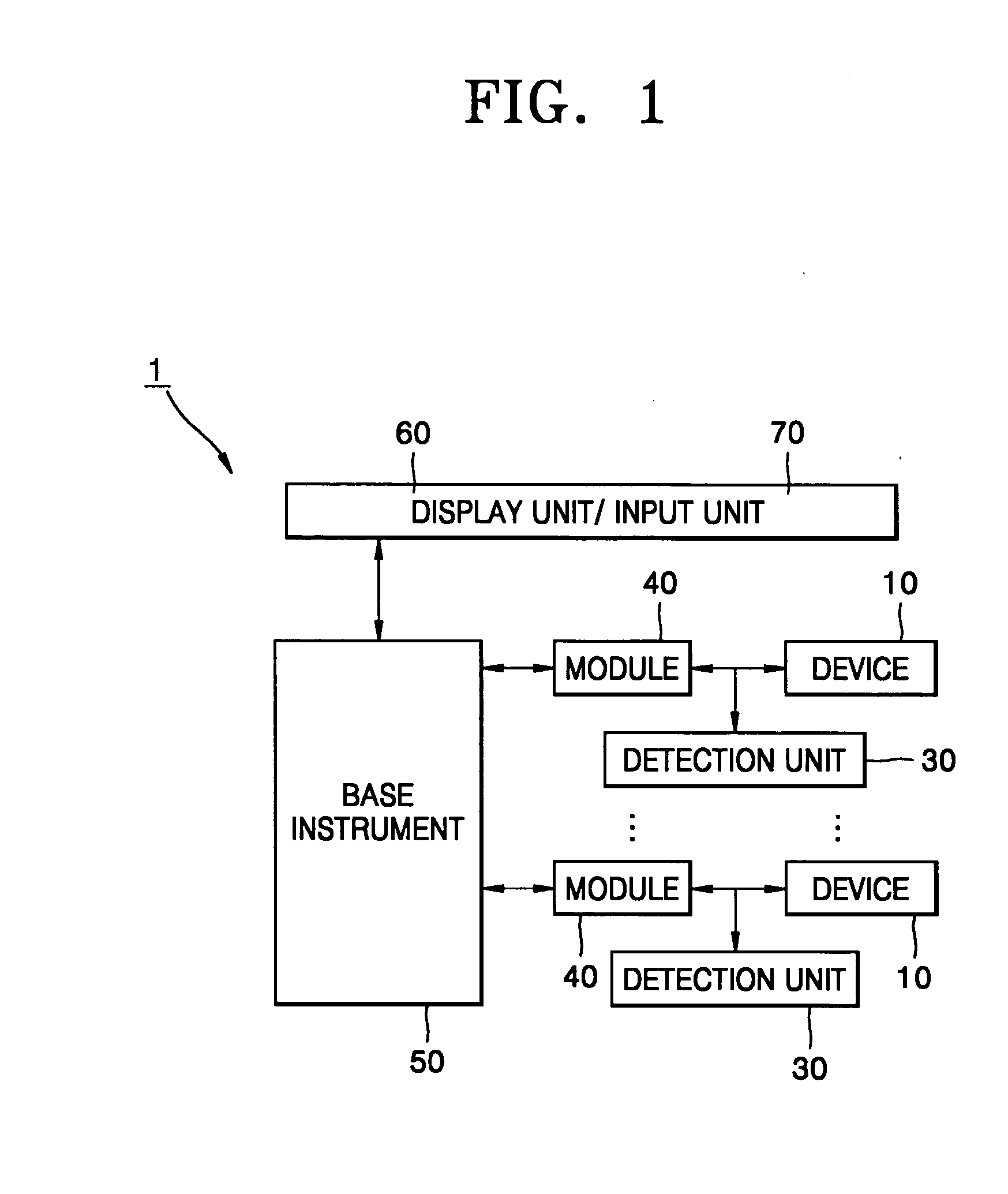
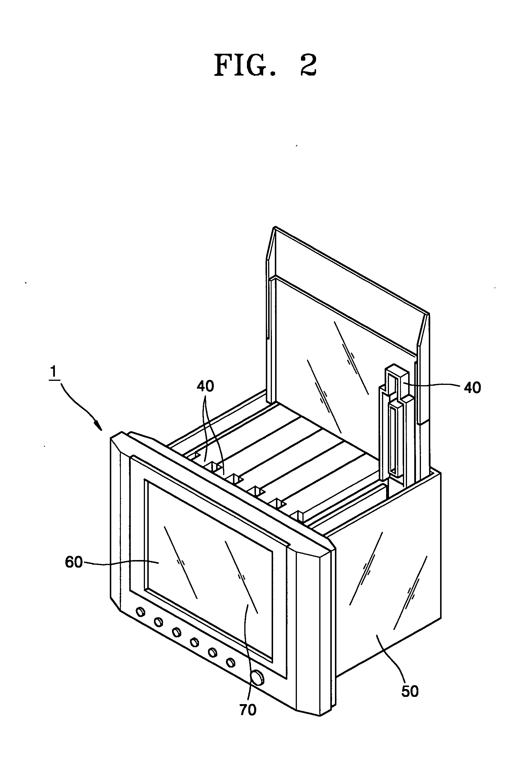
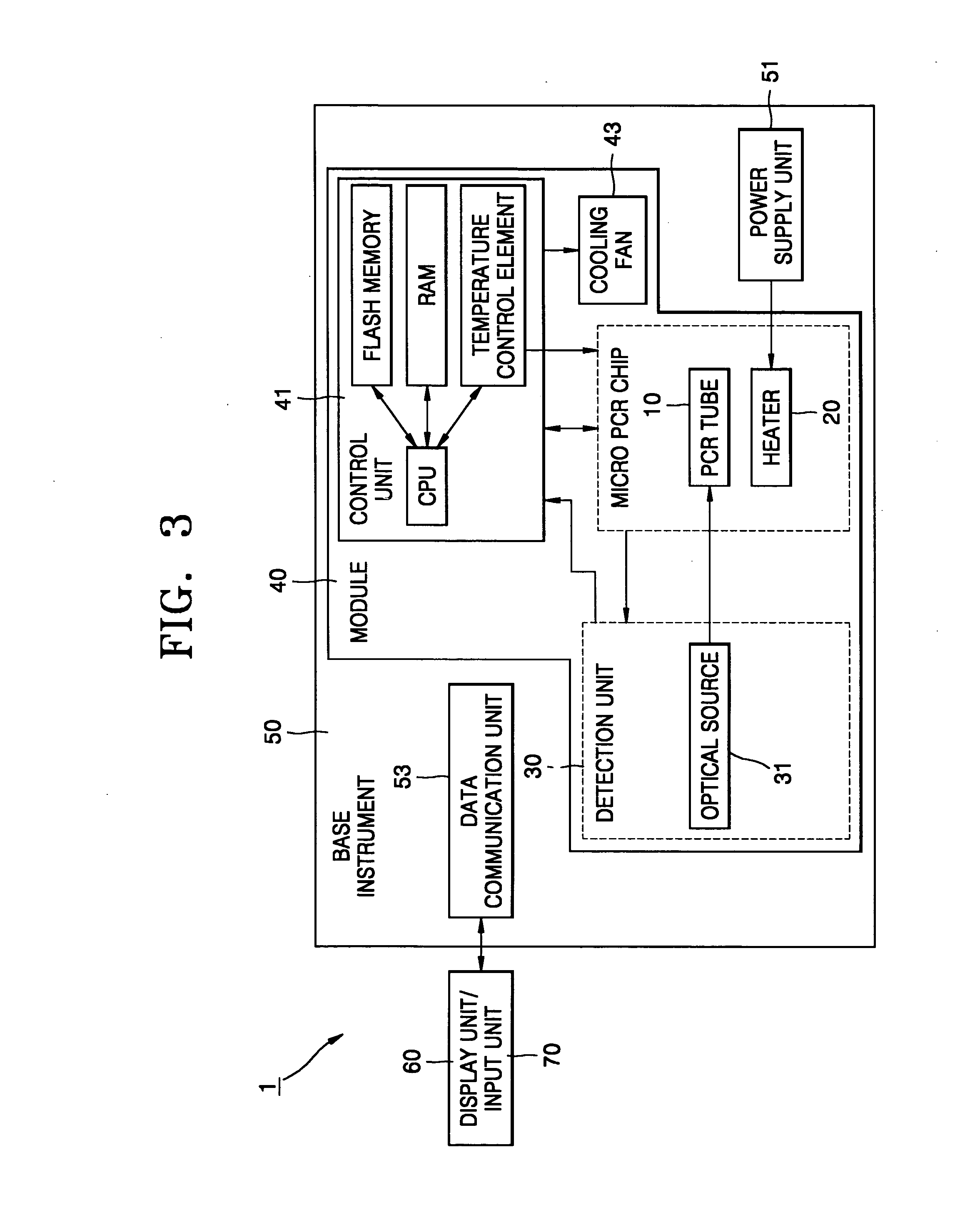
Provided are a real-time PCR monitoring apparatus and method. The real-time PCR monitoring apparatus includes a microchip-type PCR tube that has a PCR solution-containing PCR chamber, a micro-heater that applies heat to the PCR chamber of the PCR tube, a detection unit that detects a PCR product signal based on the amount of a PCR product of the PCR solution, a plurality of modules, each of which includes a cooling fan for lowering the inside air temperature and a control unit for adjusting the temperature of the PCR chamber of the PCR tube by controlling the micro-heater and the cooling fan, and receives the PCR tube, the micro-heater, and the detection unit, a base instrument that includes a power supply unit electrically connected to the modules for power supply and a data communication unit electrically connected to the modules for data communication with the control unit of each of the modules, and a display unit that displays data received from the data communication unit, wherein the control unit of each of the modules independently controls at least one of both the detection unit and the temperature of the PCR chamber of the PCR tube received in each of the modules. Therefore, co-amplification of different samples at different temperature conditions can be carried out and monitored in real time.
Description
BACKGROUND OF THE INVENTION [0001] This application claims priority from Korean Patent Application No. 2003-89352, filed on Dec. 10, 2003, in the Korean Intellectual Property Office, the disclosure of which is incorporated herein by reference in its entirety. [0002] 1. Field of the Invention [0003] The present invention relates to a real-time polymerase chain reaction (hereinafter, simply referred to as PCR) monitoring apparatus and method. More particularly, the present invention relates to a real-time PCR monitoring apparatus with a combined PCR thermal cycler and PCR product detector, and a real-time PCR monitoring method using the apparatus. [0004] 2. Description of the Related Art [0005] The science of genetic engineering originated with the discovery of restriction enzymes. Similarly, PCR technology led to an explosive development in the field of biotechnology, and thus, it may be said that the PCR technology is a contributor to the golden age of biotechnology. PCR is a techno...
Claims
Application Information
Patent Timeline
Application Date:The date an application was filed.
Publication Date:The date a patent or application was officially published.
First Publication Date:The earliest publication date of a patent with the same application number.
Issue Date:Publication date of the patent grant document.
PCT Entry Date:The Entry date of PCT National Phase.
Estimated Expiry Date:The statutory expiry date of a patent right according to the Patent Law, and it is the longest term of protection that the patent right can achieve without the termination of the patent right due to other reasons(Term extension factor has been taken into account ).
Invalid Date:Actual expiry date is based on effective date or publication date of legal transaction data of invalid patent.

