Novel wing arrangement

a technology of wing arrangement and rear planing blade, which is applied in the field of new wing arrangement, can solve the problems of unwanted water turbulence over the rear planing blade, and achieve the effect of less turbulen

Inactive Publication Date: 2005-06-16
ERB DONALD M JR +1
View PDF2 Cites 2 Cited by
  • Summary
  • Abstract
  • Description
  • Claims
  • Application Information

AI Technical Summary

Benefits of technology

[0005] the improvement wherein the front planing blade is carried lower on said arm than the rear planing blade such that the flow of water over the front planing blade produces less turbulence over the rear planing blade.
[0007] the improvement wherein the front planing blade is carried lower on said arm than the rear planing blade such that the flow of water over the front planing blade produces less turbulence over the rear planing blade.
[0010] The first embodiment reduces the impact and stress on the bolts used to hold the wing to arm and the front wing is more firmly attached to the arm when impacting the water due to the pressure now pushing the wing into the arm. The result is a stronger product with less flex from left to right. There is also a larger wing surface to the bottom of the wing due to the lack of the width of the arm being in the way and displacing water out to the side of the blade. The result is a larger planing surface and a stronger planing surface. The higher rear wing allows the board to switch its angle of attack needed in jumping the towable hydrofoil as the strut displaces and cuts through the water resulting in less resistance or drag on the rear wing. When the water hits the strut there is less resistance than when it hits the entire flat surface of the wing. The previous designs did not take this into consideration and resulted in a slower reacting hydrofoil and weaker components.

Problems solved by technology

This results in unwanted water turbulence over the rear planing blade.

Method used


Image

  • Novel wing arrangement
  • Novel wing arrangement
  • Novel wing arrangement

Examples


Embodiment Construction

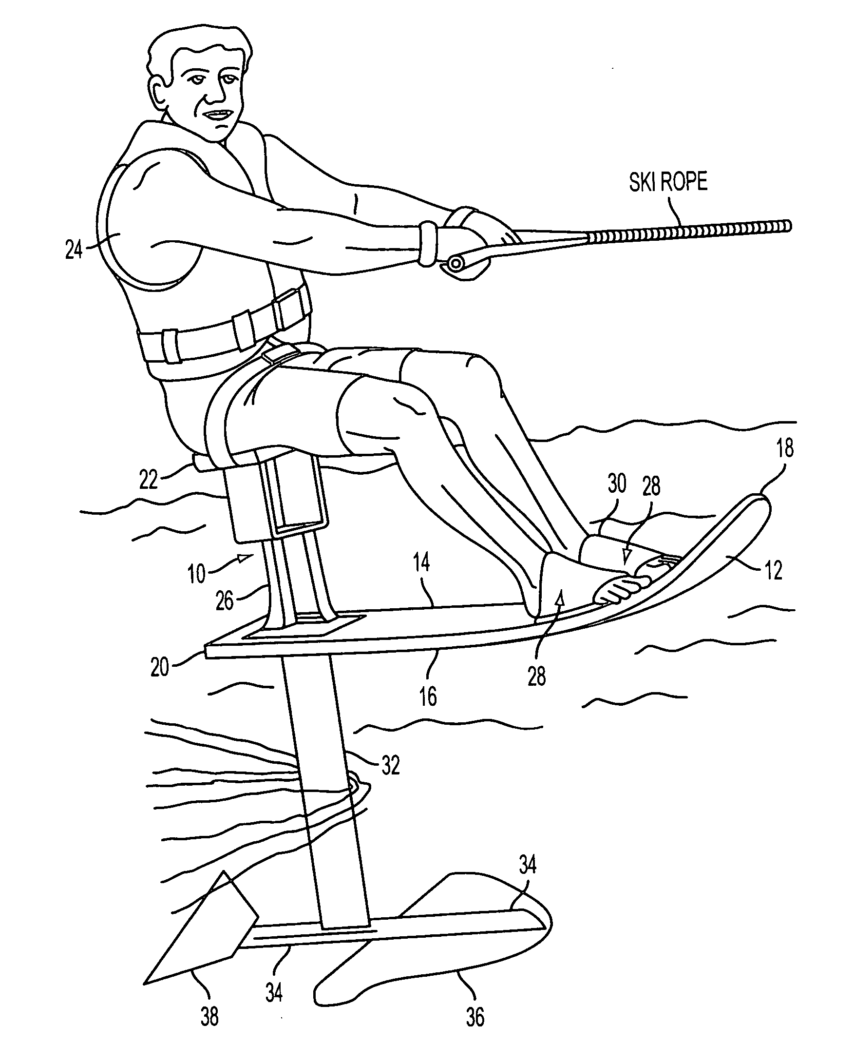
[0013] Turning to the drawings in greater detail.

[0014] Referring to FIG. 1, there is shown a “flying ski”10 which embodies the preferred design of the water sports device present invention. The flying ski 10 includes an elongate board 12 having an upper surface 14 and a lower surface 16, and a front end 18 and a back end 20. A seat 22 extends generally perpendicular to and upward from the upper surface 14 of the board for supporting the buttocks of a seated rider 24 at a point spaced above the back of the board.

[0015] The seat 22 is carried by the support member 26.

[0016] The rider's legs extend forward toward the front of the board, where they are secured by a holders 28, such as a pair of rubber sheets 30, which are attached to the board about two feet forwardly of seat 22 so as to form two elongate generally semicircular loops into which the feet of the rider can be inserted.

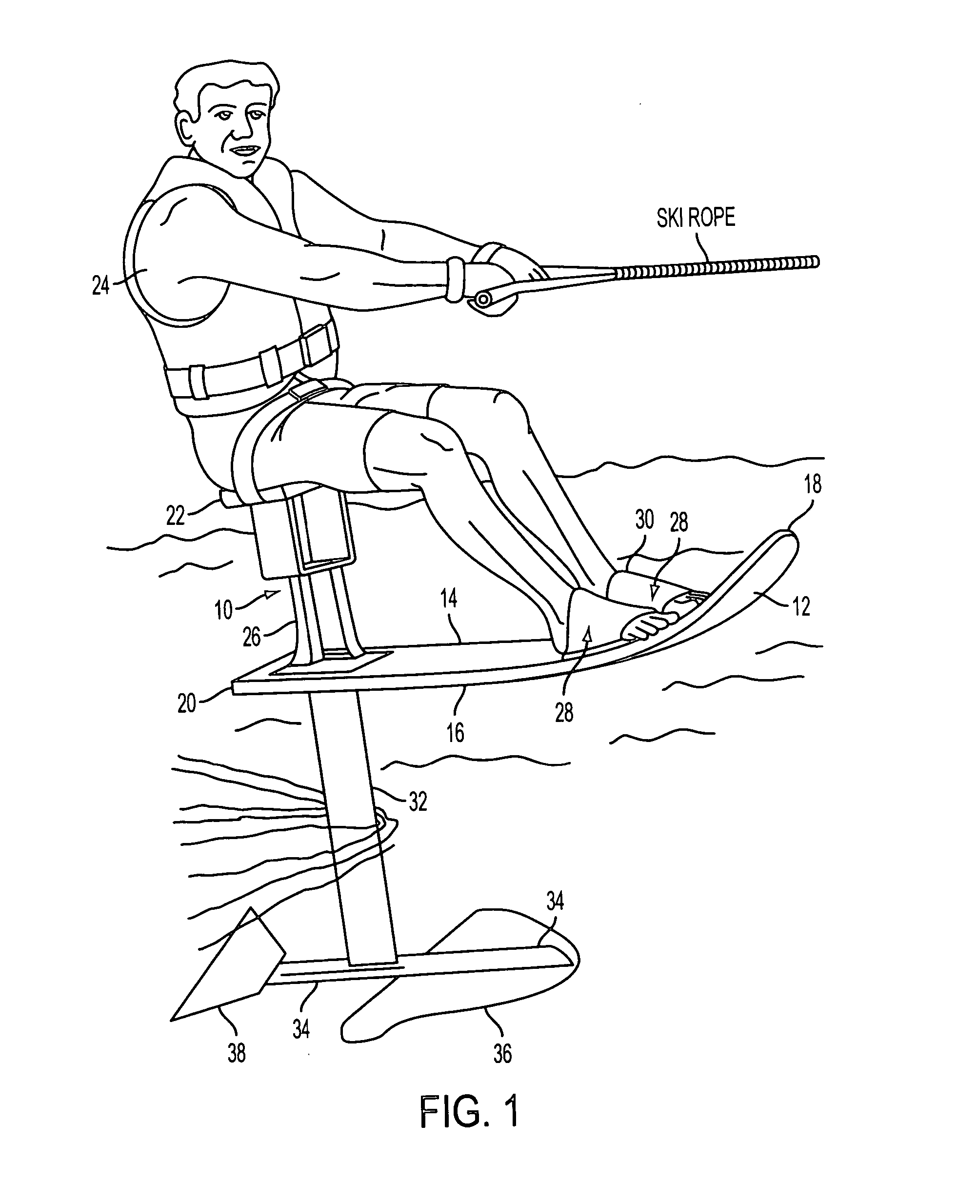
[0017] An elongate hydrofoil 32 extends generally perpendicular to and thru a tight fitting opening i...


PUM


Abstract

A water sports device for supporting a seated human rider while the rider and the device are towed behind a powered water craft, the device including an elongated board having a front end and a back end to which is secured a seat for supporting the buttocks of the rider in a position spaced from and roughly centered above the back one-third of the board, a holder for securing the feet of the rider over the top of the board secured to the board spaced at least about two feet toward the front end of the board from the seat. An elongated hydrofoil extends downward from the board and front and rear planing blades carried by an arm which is generally parallel to the board. The arm is secured to the hydrofoil and spaced from the board, so that the blades are generally parallel to the board. The planing blades provide essentially no lift when the board is horizontal, The improvement resides in the front planing blade being carried lower on the arm than the rear planing blade such that the flow of water over the front planing blade produces less turbulence over the rear planing blade. In a water sports device for supporting a standing human rider while the rider and the device are towed behind a powered water craft, the device including an elongated board having a front end and a back end, an elongated hydrofoil extends downward from the board, front and rear planing blades carried by an arm which is generally parallel to the board, said arm being secured to the hydrofoil and spaced from the board, so that the blades are generally parallel to the board, the planing blades provide essentially no lift when the board is horizontal, the improvement wherein the front planing blade is carried lower on said arm than the rear planing blade such that the flow of water over the front planing blade produces less turbulence over the rear planing blade.

Description

[0001] This patent claims the filing date of U.S. Provisional Patent Application Ser. No. 60 / 524,363, filed Nov. 24, 2003. BACKGROUND OF INVENTION [0002] U.S. Pat. Nos. 5,100,354, 5,249,998, 6,179,676 B1, 6,551,158 B2, 6,234,856 and 6,443,786 disclose water sport devices for supporting a seated human rider while the rider and the device are towed behind a powered water craft. The devices include an elongated board to which a seat and foot holders are secured. An elongate strut in the shape of a hydrofoil projects downwardly from the board. The lower end of the strut carries an arm which is generally parallel to the board. Front and rear planing blades are carried by the arm. The positioning of the rigidly mounted seat and the planing blades, the use of a single vertical strut, the size of the planing blade and the positioning of the foot holders provides a water sports device which is relatively easy to ride, while at the same time being highly maneuverable and capable of high jumps...

Claims


Application Information

Patent Timeline
Patent Type & Authority Applications(United States)
IPC IPC(8): B63B1/24B63B35/81
CPCB63B1/242B63B35/81B63B1/26B63B34/40
Inventor ERB, DONALD M. JR.MURPHY, MICHAEL J.
Owner ERB DONALD M JR
Why Eureka
Try Eureka