Metrology device for videoendoscopic probe

a technology of endoscope and probe, which is applied in the field of videoendoscope, can solve the problems of preventing the use of the entire sensitive surface of the ccd sensor connected to the lens, affecting the accuracy of the measurement, and only being used for repetitive measurements

Active Publication Date: 2005-06-16
TOKENDO
View PDF13 Cites 15 Cited by
  • Summary
  • Abstract
  • Description
  • Claims
  • Application Information

AI Technical Summary

Benefits of technology

[0055] Advantageously, the fixing means are formed on a locking tube which is mobile in an axial manner on the optical head between distal and proximal positions, and are brought back to the distal position by resilient return means, the coupling means being of the type male-female and placed in such a way so as to arrive in a coupled position at the end of a locking path of the locking means under the effect of the resilient return means.

Problems solved by technology

This method is also only applicable to rigid endoscopes and only for repetitive measurements performed on identical targets.
Nevertheless, the three stereo devices described above that allow obtaining such a result present significant, even redhibitory drawbacks as regards to their integration into a very small diameter videoendoscopic probe.
Indeed, the integration of two axial view lenses in the axial end of a videoendoscopic probe requires the implementation of very small diameter lenses which prevent the entire sensitive surface of the CCD sensor connected to the lenses to be used.
These limitations are not directed at the optimization of the accuracy of the measurement process.
Furthermore, the integration into the distal end of a videoendoscopic probe of an image splitting device that have concave rectilinear transversal profiles becomes difficult to perform due to the miniaturization difficulties of such a device.
Nonetheless, the optical measuring field of such a prism turns out to be, in principle, less than 15 degrees, a value that is clearly insufficient for an endoscopic measurement system.

Method used


Image

  • Metrology device for videoendoscopic probe
  • Metrology device for videoendoscopic probe
  • Metrology device for videoendoscopic probe

Examples


Embodiment Construction

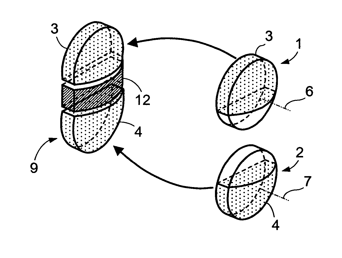
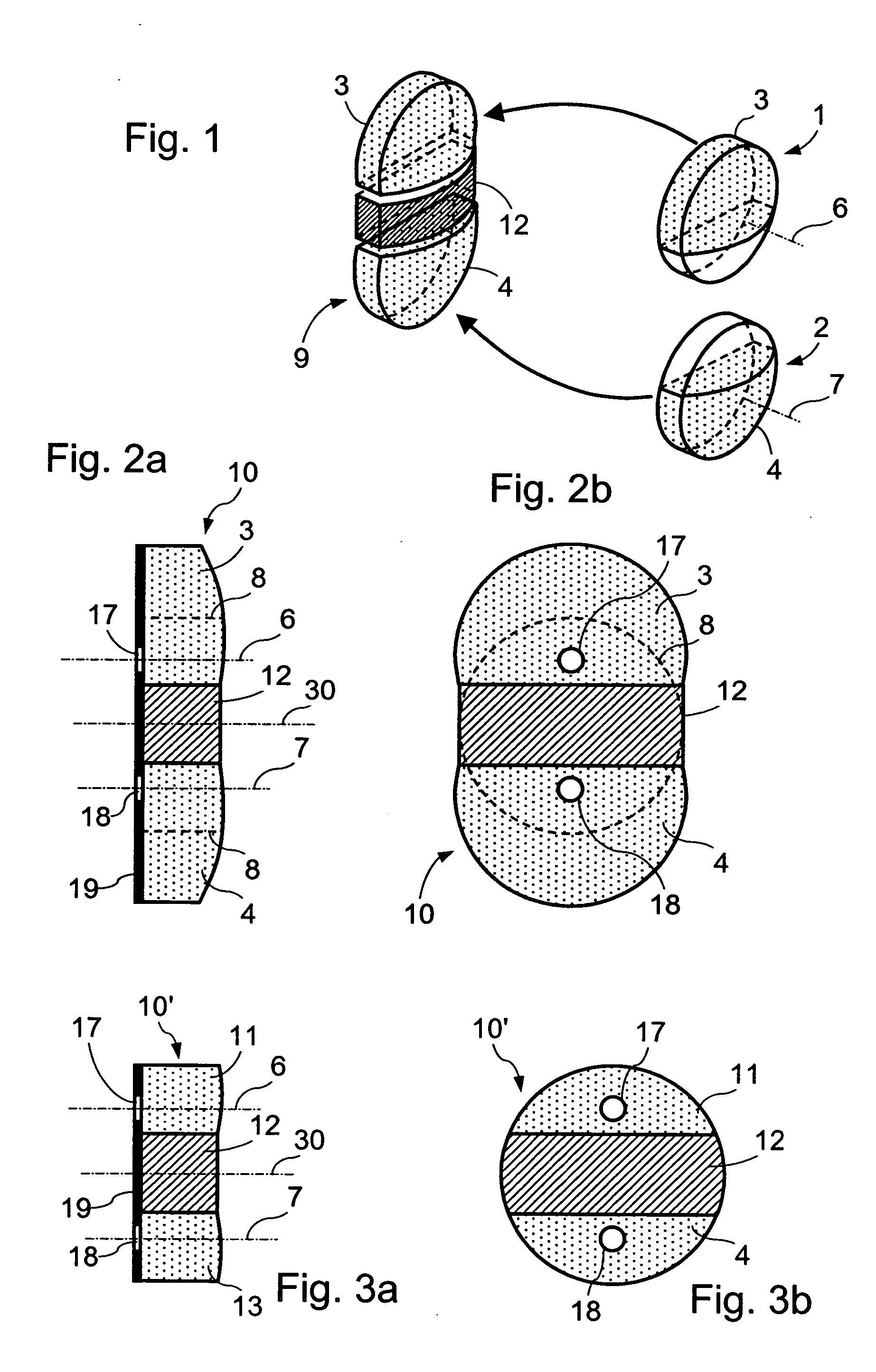
[0079]FIG. 1 schematically represents the structure of an image splitting optical component 10 according to the invention.

[0080] The optical component 9 shown on this figure is obtained by bringing together an opaque central element 12 and two identical side sections 3, 4 of lenses 1, 2 larger than a half-lens or half-moon in order to include the optical axes 6, 7 of the lenses 1, 2. Each of these lens sections is obtained by cutting a convergent lens 1, 2, for example according to a cutting plane parallel to the optical axis of the lens, the convergent lens having a flat face and a convex face. The optical component 9 shown in FIG. 1 thus presents two perpendicular symmetry planes, namely, a mediator plane of the central element 13 dividing each of the two lens sections and the central element into two symmetrical parts and a mediator plane of the central element on either side of which the two lens sections are placed symmetrically.

[0081]FIGS. 2a and 2b show a front and profile ...


PUM


Abstract

Image splitting device for videoendoscope, comprising an image splitting optical component to form on the sensitive surface of a video sensor housed in the distal end part of a videoendoscope a single composite image formed from two images of an observed target, viewed from two different angles; the image splitting optical component comprises two sections of identical convergent lenses, integrated into an opaque central element, maintaining the space between the two section of lenses, each of the two sections of lenses are at least equal to a half-moon so that it is crossed by the optical axis of the lens

Description

BACKGROUND OF THE INVENTION [0001] 1. Field of the Invention [0002] The invention relates to videoendoscopes equipped with a device for measuring the dimensions of a target located in the observation field of the videoendoscope. [0003] It is particularly, but not exclusively, applicable to industrial endoscopy. [0004] 2. Description of the Prior Art [0005] Normally, the term “endoscope” is given to a flexible or rigid probe, designed to be inserted into an obscure cavity and allowing the user to observe through an eyepiece the image of a target located inside the cavity. To this end, an endoscope comprises a lighting device of the target and an optical device providing the user with an image of the target. The optical device comprises a distal lens, an image transportation device that may be rigid and composed of a series of lenses, or flexible composed of a bundle of sorted optical fibers, and a proximal eyepiece in which the user can observe the image of the target. The lighting d...

Claims


Application Information

Patent Timeline
Patent Type & Authority Applications(United States)
IPC IPC(8): A61B1/00A61B1/005G02B23/24
CPCA61B1/00193A61B1/04A61B5/1076H04N2005/2255H04N5/2254H04N13/0217H04N13/044G02B23/2423H04N13/344H04N13/218H04N23/555H04N23/55
Inventor ROVEGNO, JEAN
Owner TOKENDO
Why Eureka
Try Eureka