Ultrasound system for generating a single set of ultrasound pulse firings

a technology of ultrasound pulse firing and ultrasound system, which is applied in the field of ultrasonic imaging, can solve the problems of undesirable temporal anomalies in the image, and the inability to generate additional energy,

Inactive Publication Date: 2005-06-16
SHENZHEN MINDRAY BIO MEDICAL ELECTRONICS CO LTD
View PDF71 Cites 47 Cited by
  • Summary
  • Abstract
  • Description
  • Claims
  • Application Information

AI Technical Summary

Problems solved by technology

Since the data are recorded using two different sets of ultrasound pulses, generated at different times, the displayed image may contain undesirable temporal anomalies.
This additional energy may be considered undesirable.

Method used


Image

  • Ultrasound system for generating a single set of ultrasound pulse firings
  • Ultrasound system for generating a single set of ultrasound pulse firings
  • Ultrasound system for generating a single set of ultrasound pulse firings

Examples


Embodiment Construction

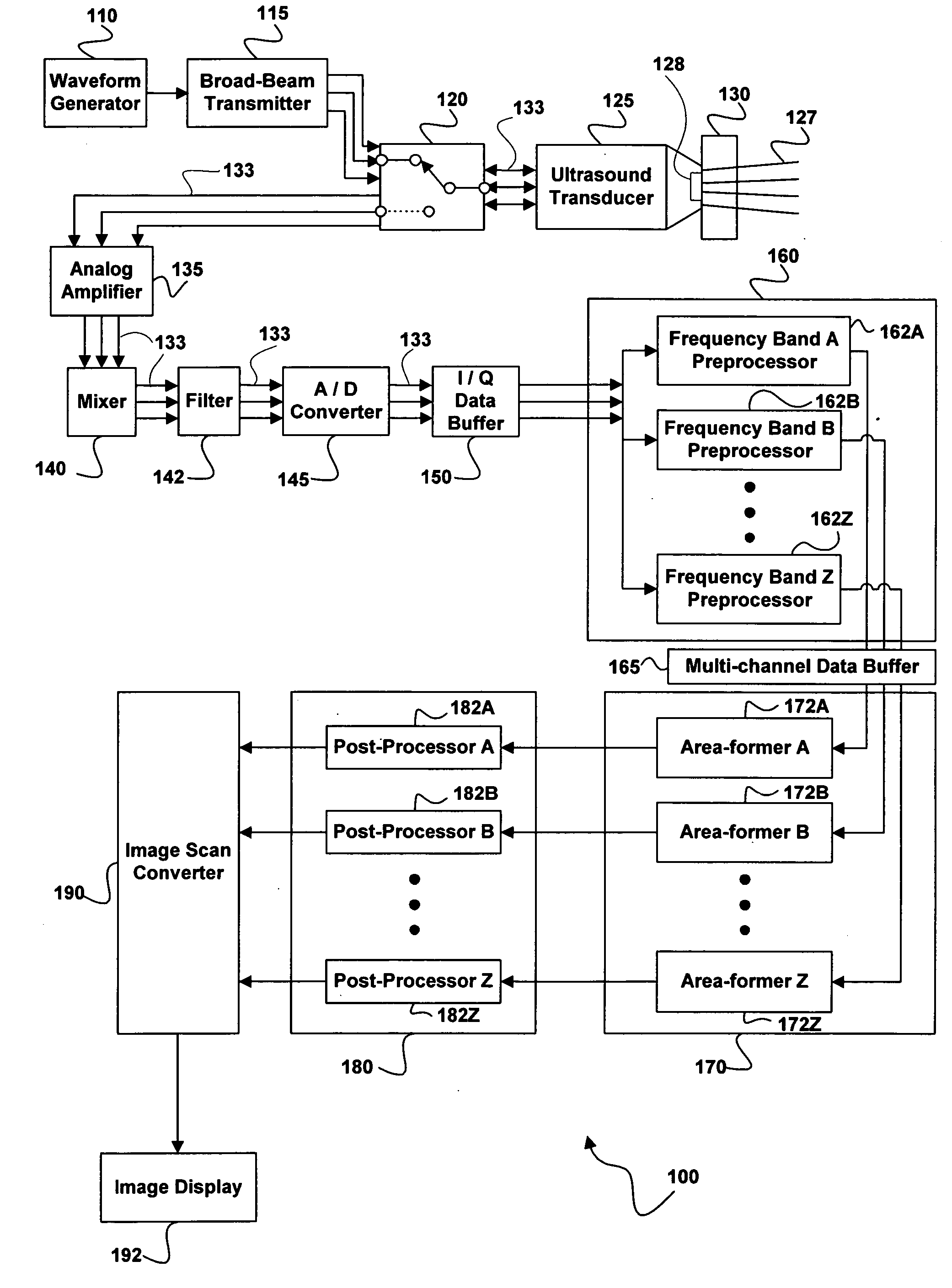
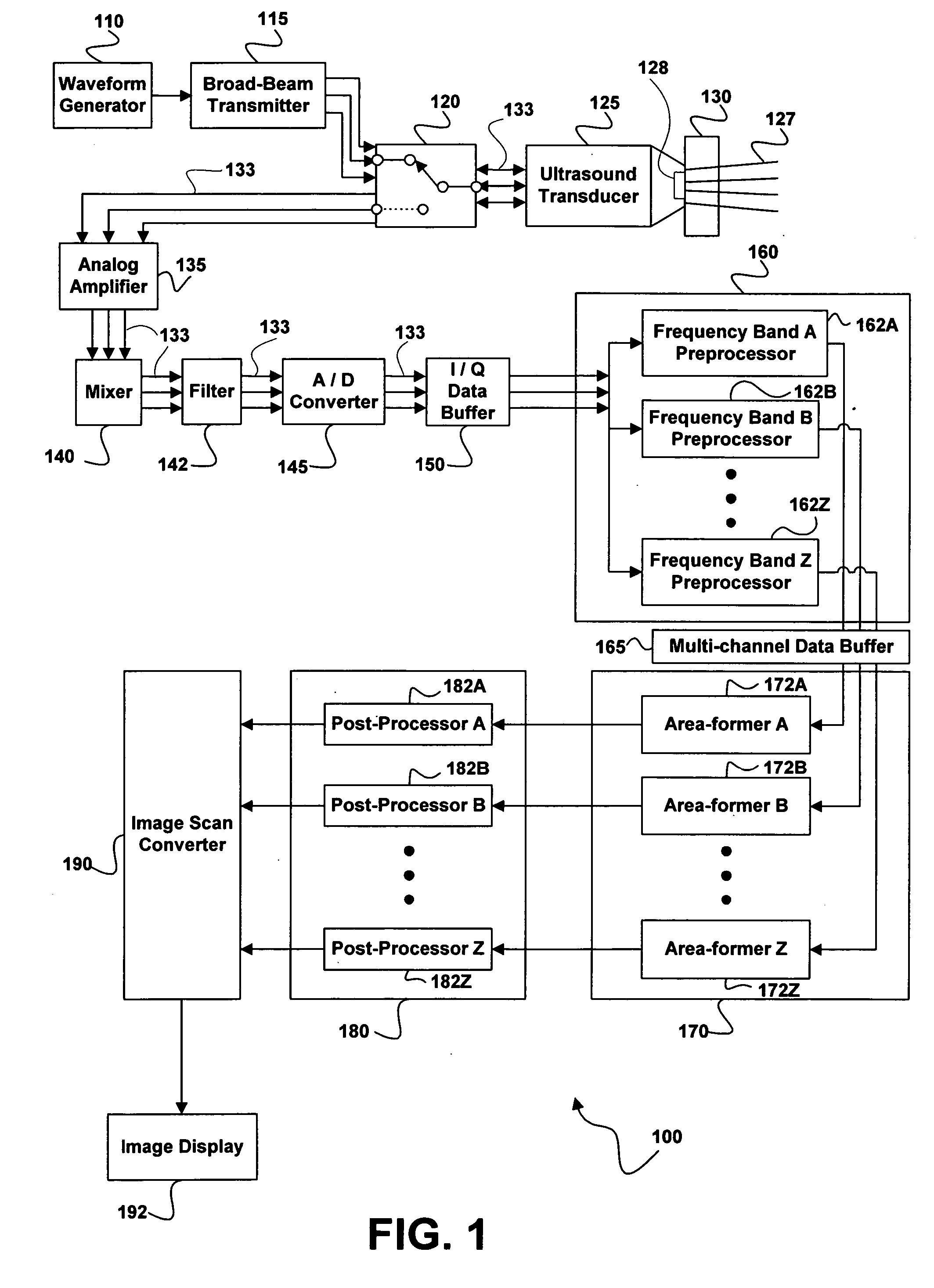
[0021]FIG. 1 is a block diagram showing an embodiment of the present invention generally designated system 100. System 100 includes a waveform generator 110 that produces waveforms having a plurality of pulses. These pulses are optionally of differing or multiple frequencies. The output of waveform generator 110 is coupled to a broad-beam transmitter 115. Broad-beam transmitter 115 splits the input waveform into multiple channels, amplifies the signal, and / or applies delays required to form a broad-beam ultrasound wave. Broad-beam technology reduces the number of transmitted pulses required to image an area and enables use of area-forming techniques in place of prior art beam-forming methods. In an alternative embodiment broad-beam transmitter 115 is replaced by a prior art beam transmitter. The output of broad-beam transmitter 115 is coupled through a multi-channel transmit / receive switch 120 and used to drive an ultrasound transducer 125. Ultrasound transducer 125 sends ultrasound...


PUM

PropertyMeasurementUnit
transmit frequencyaaaaaaaaaa
frequencyaaaaaaaaaa
imagingaaaaaaaaaa

Abstract

An ultrasound imaging system configured to simultaneously acquire and process multi-mode and multi-band echo information from a single set of pulse firings is provided. Raw ultrasound signals are digitized and stored in an I / Q data buffer. The stored data are then parallel preprocessed as a function of frequency band or alternative encoding. Parallel preprocessing optionally includes manipulating the data in respect to different imaging modes. Outputs of the parallel preprocessors are coupled to separate area formers used to simultaneously reconstruct various desired echo information to form a multi-mode or multi-band image. The echo formation process is optionally performed in parallel.

Description

CROSS-REFERENCES TO RELATED APPLICATIONS [0001] This application is a continuation of and claims the priority benefit of U.S. patent application Ser. No. 10 / 039,862 filed Oct. 20, 2001 and entitled “Simultaneous Multi-Mode and Multi-Band Ultrasonic Imaging,” now U.S. Pat. No. ______. This application is related to U.S. patent application Ser. No. 10 / 039,922 filed Oct. 20, 2001 and entitled “Block Switching in Ultrasound Imaging,” now U.S. Pat. No. 6,773,399. The subject matter of these commonly owned applications is incorporated herein by reference.BACKGROUND [0002] 1. Field of the Invention [0003] The present invention is in the field of imaging devices and more particularly in the field of ultrasonic imaging. [0004] 2. Description of the Prior Art [0005] Ultrasonic imaging is a frequently used method for examining a wide range of materials. The method is especially common in medicine because of its relatively non-invasive nature, low cost, and fast diagnostic cycles. Typically, ul...

Claims


Application Information

Patent Timeline
Patent Type & Authority Applications(United States)
IPC IPC(8): G01N29/44A61B8/00G01N29/06G01N29/11G01N29/34G01S7/52G01S15/89G03B42/06
CPCG01N29/06G01N29/0609G01N29/11G01N29/348G01N2291/017G03B42/06G01N2291/02416G01N2291/02466G01S7/52023G01S15/8954G01N2291/0228
Inventor JI, TING-LANMCLAUGHLIN, GLEN
Owner SHENZHEN MINDRAY BIO MEDICAL ELECTRONICS CO LTD
Why Eureka
Try Eureka