Shell plating developing method, shell plating manufacturing method, computer program for teaching the methods, and image recording medium for teaching the methods

a shell plating manufacturing and developing method technology, applied in the field of shell plating manufacturing methods, shell plating developing methods, computer programs to teach the methods, etc., can solve the problems of unnecessarily large machining of the developing flat plate into the shell plating, and the inability to achieve excellent machining efficiency, so as to improve the efficiency of machining

Inactive Publication Date: 2005-06-16
COOP ASSOC OF JAPAN SHIPBUILDERS THE +1
View PDF3 Cites 2 Cited by
  • Summary
  • Abstract
  • Description
  • Claims
  • Application Information

AI Technical Summary

Benefits of technology

[0008] According to the invention, the flat plate is bent along the second connection line developed on the flat plate so as to bend the first connection line developed on the flat plate as well, thereby forming an intermediate curved plate. Thereafter, the intermediate curved plate is shrunk or extended in the direction of the second connection line to manufacture the shell plating of predetermined shape. In manufacturing the shell plating, how the flat plate should be bent, or how the intermediate curved plate should be shrunk or extended is clarified by the first and second connection lines. Therefore, the shell plating of predetermined shape can be easily manufactured from the flat plate even by person other than the skilled worker.
[0011] According to the invention, the second connection line is developed from the shell plating on the flat plate in such a way that the integrated value of the amount of machining corresponding to the shrinkage ratio or the extension ratio of the second connection line is minimum, thereby leading to reduction of the amount of machining corresponding to the shrinkage ratio or the extension ratio of the flat plate required in manufacturing the shell plating and improvement of the efficiency in machining the shell plating as compared with the conventional methods.
[0012] Also, the invention provides the shell plating developing method, wherein the first connection line is developed as a straight line on the flat plate while the length of the first connection line is maintained, and the second connection line is developed on a flat plate as a line constituting a flat plate lattice system along with said straight line and orthogonal to the straight line at each lattice point of the flat plate lattice system in such a way that the integrated value of the amount of machining corresponding to the expansion ratio or the shrinkage ratio of the second connection line is minimum.
[0013] Further, the invention provides the shell plating developing method, wherein when the first and second connection lines are developed from the shell plating to the flat plate, a shell plating fraction area of the shell plating containing the first and second connection lines is determined, a developable surface is determined in which the first connection line contained in the shell plating fraction area is developed as a straight line while the length of the first connection line is kept invariable, and the second connection line contained in the shell plating fraction area is developed in such a way that the integrated value of the amount of machining corresponding to the expansion ratio or the shrinkage ratio is minimum, and the shell plating fraction area is developed on a part of the developable surface, the part of the developable surface is developed on a flat plate fraction area, and the first or second connection lines corresponding to the adjacent flat plate fraction areas are connected.
[0016] Also, the invention provides the shell plating developing method, wherein the second connection lines are interconnected in such a way that a dislocation between the second connection lines contained in the adjacent flat plate fraction areas is minimized by the least square method.

Problems solved by technology

However, according to a knowledge of the inventor of this application, it is difficult to say that the machining of the shell plating from the flat plate developed by the geodesic line developing method is suitable for the shell plating especially in a bow and stern portion with large curvature.
That is, it cannot be said that the shell plating is optimally developed to the flat plate, and the amount of machining the developing flat plate into the shell plating becomes unnecessarily large, so that the machining efficiency is not always excellent.

Method used


Image

  • Shell plating developing method, shell plating manufacturing method, computer program for teaching the methods, and image recording medium for teaching the methods
  • Shell plating developing method, shell plating manufacturing method, computer program for teaching the methods, and image recording medium for teaching the methods
  • Shell plating developing method, shell plating manufacturing method, computer program for teaching the methods, and image recording medium for teaching the methods

Examples


Embodiment Construction

[0035] The embodiments of a shell plating developing method, a shell plating manufacturing method, a computer program for teaching the methods, and an image / voice recording medium according to the invention will be described below with reference to the accompanying drawings.

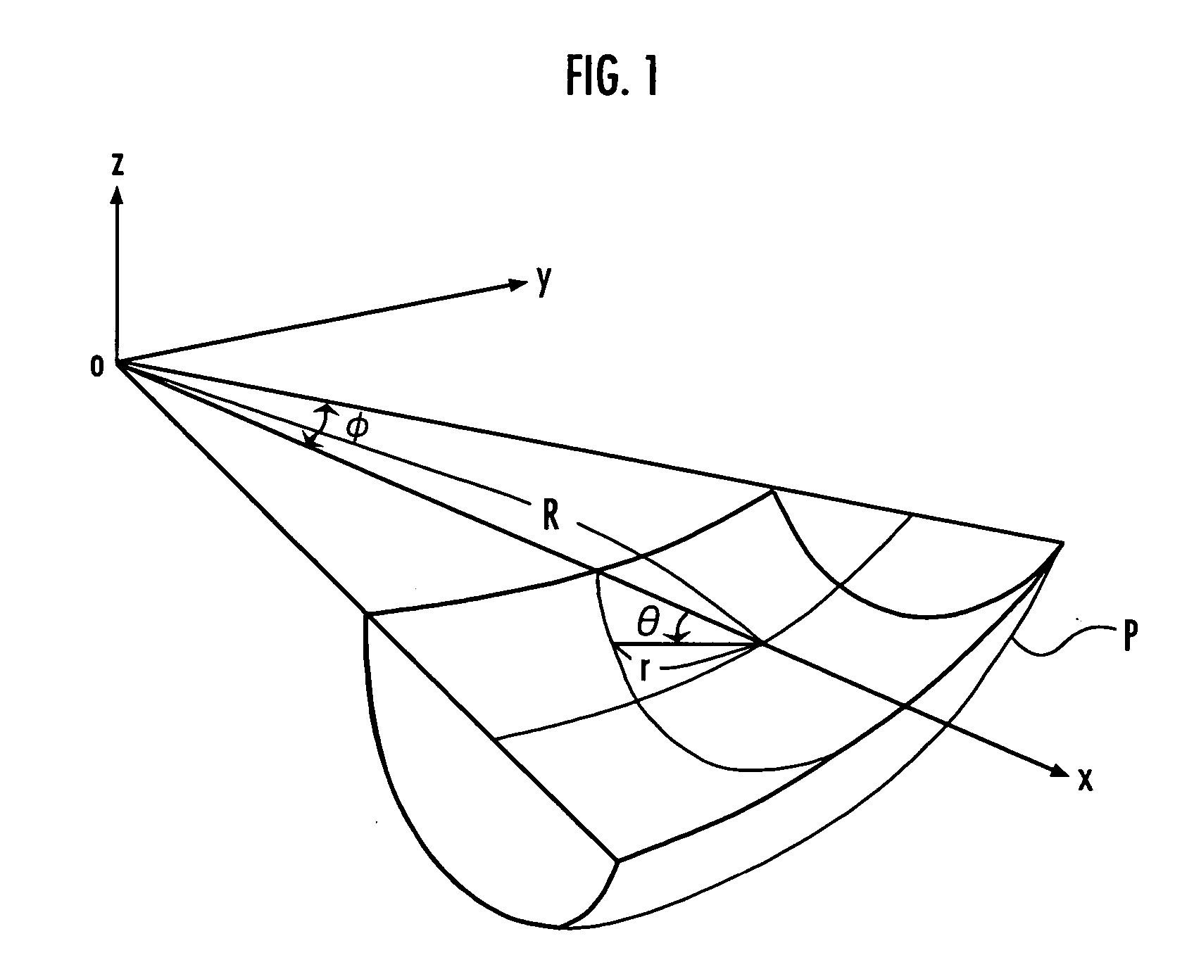
[0036] An applicational object of the shell plating developing method is represented by the following expression (1), and a shell plating P constituting a fraction of a tours obtained by rotating a circle of radius r centered at (R, 0) on the x-y flat plate around the z axis, as shown in FIG. 1.

(x−R cos φ)2+(y−R sin φ)2+z2=r2−0.4[rad]≦φ≦0.4[rad]z≦0   (1)

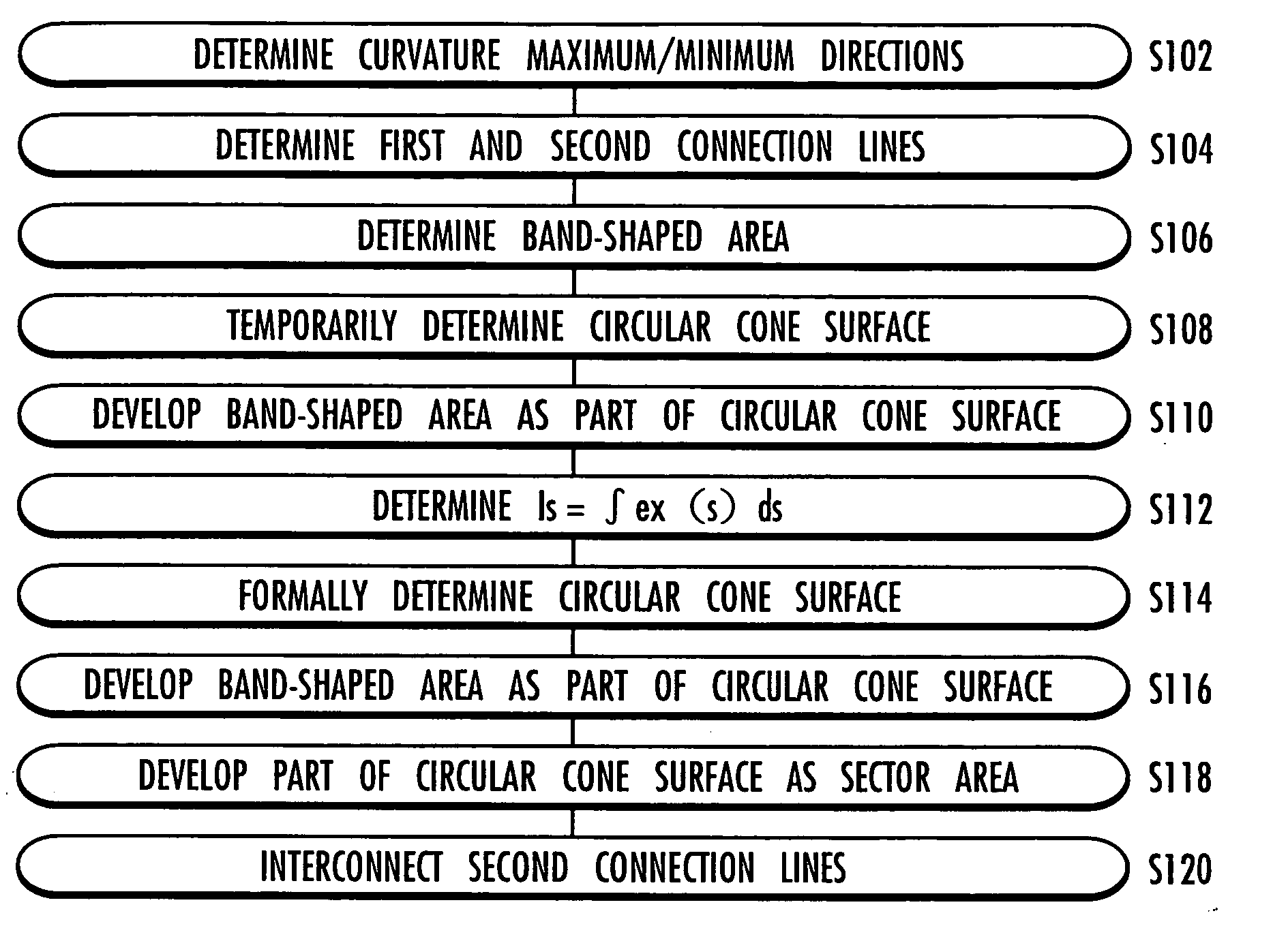
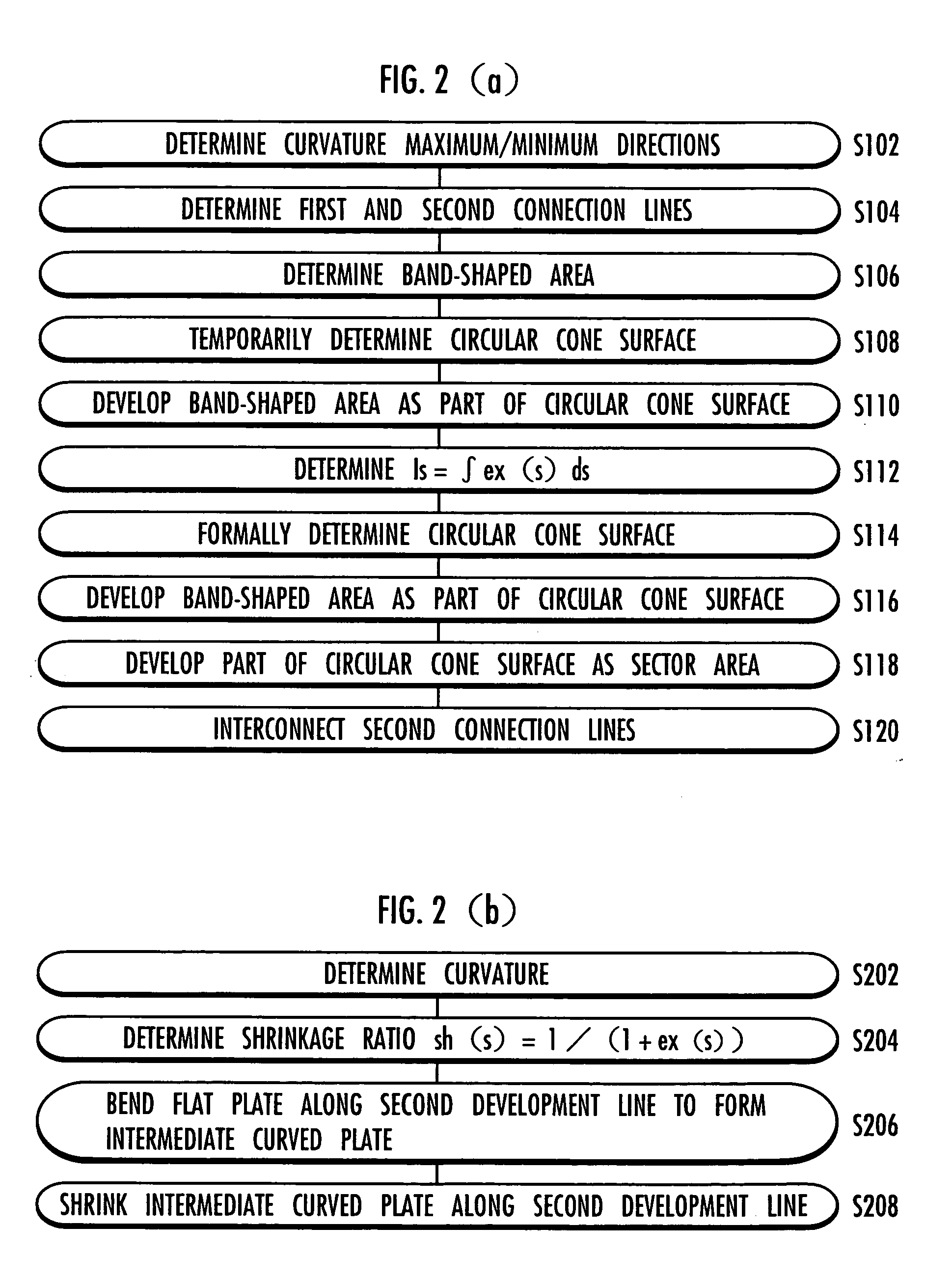
[0037] Referring to FIGS. 2 to 10, a procedure of the shell plating developing method will be described.

[0038] Firstly, the directions (arrows {circle over (1)} and {circle over (2)} in FIG. 3) in which the curvature of the shell plating P (=(radius of curvature)−1) is maximum and minimum, including plus and minus, at a point (X, Y) on the shell plating P are ...


PUM

PropertyMeasurementUnit
shrinkage ratioaaaaaaaaaa
shapeaaaaaaaaaa
curvatureaaaaaaaaaa

Abstract

The present invention provides a shell plating developing method leading to reduction of the amount of machining and improvement of the efficiency in manufacturing the shell plating. In the shell plating developing method according to the invention, a shell plating lattice system is constituted, and the directions in which the curvature of a shell plating P at each lattice point of the shell plating lattice system is maximum and minimum are determined (s102). Also, lines extending in the directions in which the absolute value of the curvature is large and small are determined as a first connection line L1 and a second connection line L2 (s104). The first connection line L1 is developed as a straight line on a flat plate P′ while the length of the first connection line L1 is maintained. And the second connection line L2 is developed as a line perpendicular to the straight line on a flat plate P″ in such a way that the integrated value of the amount of machining corresponding to the extension ratio or the shrinkage ratio of the second connection line L2 is minimum.

Description

TECHNICAL FIELD [0001] The present invention relates to a method for developing a shell plating of a predetermined shape to a flat plate, a method for manufacturing the shell plating of predetermined shape from the flat plate, a computer program for teaching the methods, and an image / sound recording medium for teaching the methods. BACKGROUND ART [0002] A metallic shell plating of a predetermined shape for the marine vessel is manufactured by developing the shell plating on a metallic flat plate and bending the flat plate in the predetermined shape. To accurately machine the flat plate into the shell plating of predetermined shape, it is required that the shell plating is appropriately developed on the flat plate. [0003] Conventionally, the shell plating developing methods typically include a geodesic line developing method, a diagonal line developing method, an orthogonal forward method, and an orthogonal return method. With the geodesic line developing method, a plurality of plane...

Claims


Application Information

Patent Timeline
Patent Type & Authority Applications(United States)
IPC IPC(8): B63B3/16B63B9/00B63B9/06G05B19/41G06F17/50
CPCB63B3/16G05B19/41B63B9/06B63B9/001B63B71/00B63B73/50
Inventor MATSUOKA, KAZUJOSHIMATSUKAWA, TADASHI
Owner COOP ASSOC OF JAPAN SHIPBUILDERS THE
Why Eureka
Try Eureka