
Programmable controller and communication interface therefor

a technology of communication interface and programmable controller, which is applied in the direction of electrical programme control, program control, instruments, etc., can solve the problems that the set data and history data of external general-purpose devices cannot be read out by such computers and programmable display devices during protocol macro execution

Inactive Publication Date: 2005-06-16
ORMON CORP
View PDF3 Cites 9 Cited by
  • Summary
  • Abstract
  • Description
  • Claims
  • Application Information

AI Technical Summary

Benefits of technology

[0012] It is therefore an object of this invention to provide a programmable controller (PLC) with gateway function of access from peripheral devices through a communication interface to external general-purpose devices such that command-response communication between the PLC and the external general-purpose devices need not be stopped during the protocol macro execution.
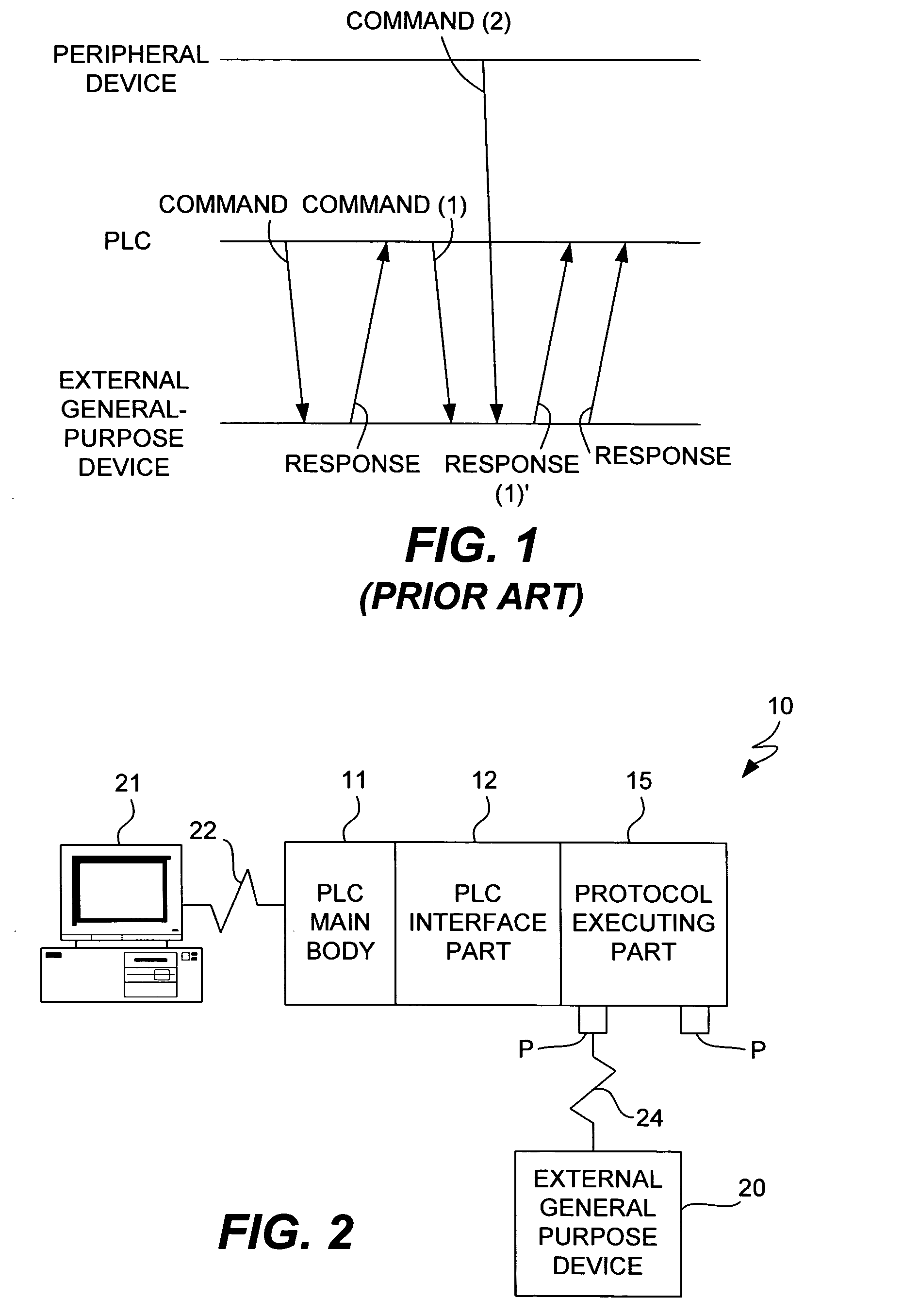
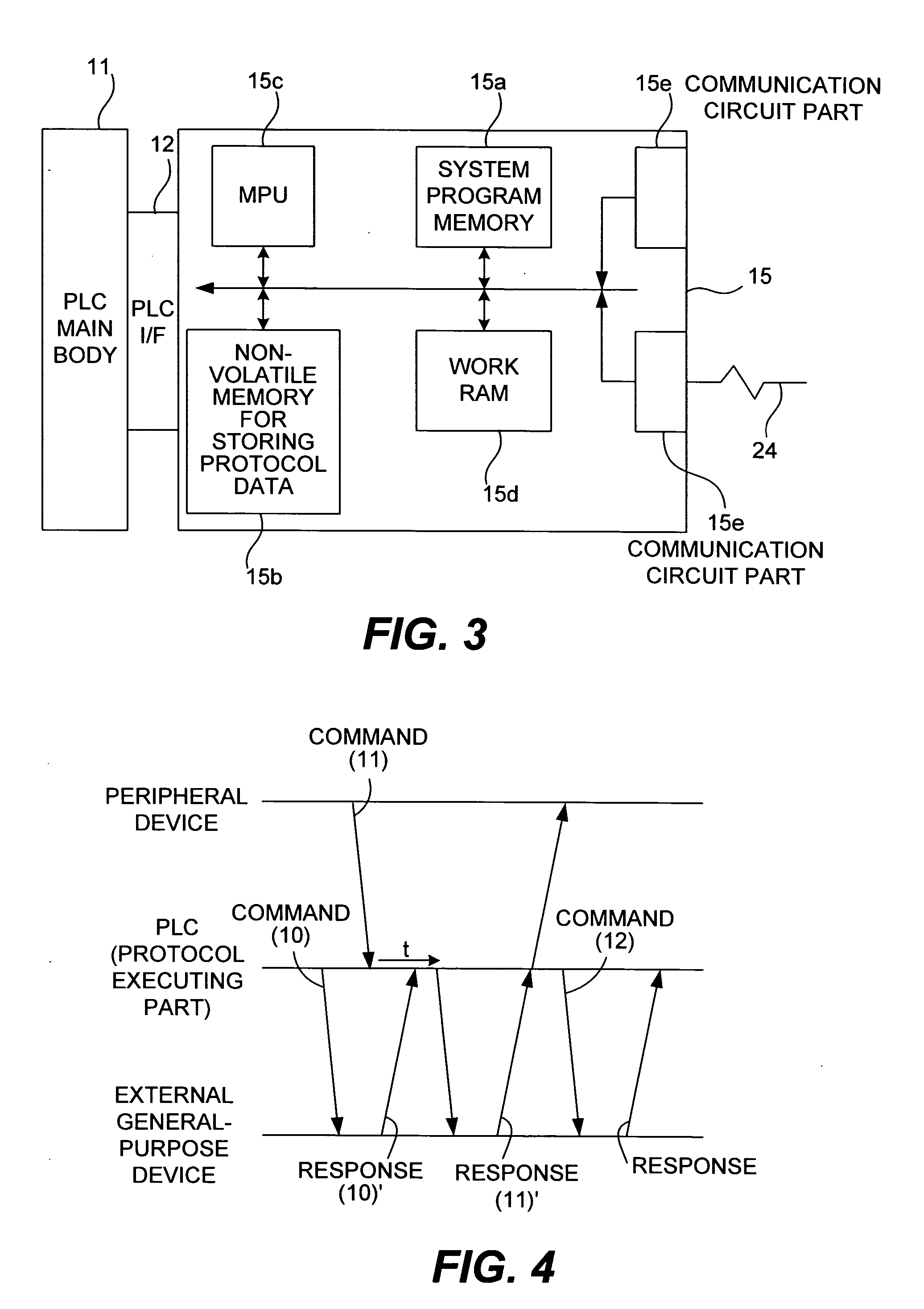
[0018] As a result, when a response is received by the communication interface, it is guaranteed that this response corresponds to the command that was transmitted immediately before. Since the communication interface (or the programmable controller) can thus recognize the origin of the command corresponding to the response (that is, whether it is itself or a peripheral device), a response can be returned to the origin of the command without committing an error. In other words, the gateway function for a direct access from a peripheral device can be used even during a communication between the communication interface and an external general-purpose device, say, by a protocol macro.

Problems solved by technology

When it becomes necessary to monitor the condition of an external general-purpose device or to set specified data on an external general-purpose device from such a computer or a programmable display device, conventional systems read and write data through the PLC since such peripheral devices cannot directly access the external general-purpose devices.
It now goes without saying that this can be a cause of an wrongful operation.
This, however, generates the problem that set data and history data of external general-purpose devices cannot be read out by such computers and programmable display devices during the protocol macro execution.

Method used


Image

  • Programmable controller and communication interface therefor
  • Programmable controller and communication interface therefor
  • Programmable controller and communication interface therefor

Examples


Embodiment Construction

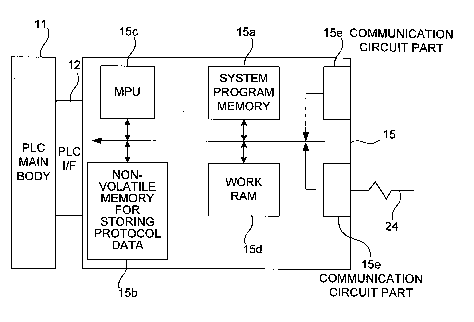
[0029]FIG. 2 shows an example of network system to which the present invention may be applied, having an external general-purpose device 20 connected to a PLC 10 and a computer 21 which serves as one of peripheral devices for directly accessing this external general-purpose device 20 and is also connected to the PLC 10. The PLC 10 is of a structure with a plurality of units connected together, inclusive of a protocol executing part 15 serving as a communication interface and connected to a PLC main body 11 through a PLC interface part 12.

[0030] Although not shown in detail, the PLC main body 11 comprises a CPU unit for cyclically executing a user program, an electrical power source unit, a communication unit and other units of various kinds. The computer 21 which functions as a monitoring tool, a setting tool or the like is connected to this PLC main body 11 through a specified line 22, which may be an In thernet (tradename) or other types of network line or a dedicated cable line ...


PUM


Abstract

A communication interface, as a part of a programmable controller, serves to carry out command-response communications with an external general-purpose device connected through a specified communication line according to an execution command from a user program for controlling a control device connected to the programmable controller or according to a preliminarily stored program. When a communication command addressed to an external general-purpose device is received from a peripheral device, it is converted appropriately for communication through a serial line. When it is relayed to the external general-purpose device, it is judged whether it is in a wait condition for a response and the relaying is temporarily stopped. When the wait condition ends, communication is carried out with the external general-purpose and the converted command is relayed to the external general-purpose device.

Description

[0001] Priority is claimed on Japanese Patent Applications 2003-391445 filed Nov. 20, 2003 and 2004-329487 filed Nov. 12, 2004. BACKGROUND OF THE INVENTION [0002] This invention relates to a programmable controller and a communication interface therefor, as well as a network system including such a programmable controller. [0003] Programmable controllers (PLCs) used in factory automation are adapted to input ON / OFF data from input devices such as switches and sensors and to carry out logical calculations according to a sequence program (user program) written in the ladder language or the like, carrying out a control by outputting signals on the ON / OFF data to output devices such as valves and actuators. A PLC system, on the other hand, is formed by combining units of different kinds such as a CPU unit which carries out the user program, an I / O unit for handling ON / OFF signals, being connected to input / output devices, a communication unit for carrying out network communication, being...

Claims


Application Information

Patent Timeline
Patent Type & Authority Applications(United States)
IPC IPC(8): G05B19/042G05B19/05
CPCG05B19/0423G05B2219/15021G05B2219/15018G05B19/054
Inventor SAWA, KAZUYAMURAYAMA, SHINJI
Owner ORMON CORP
Learn More