Method and apparatus for video signal skew compensation

a video signal and skew compensation technology, applied in the field of kvm switches and the transmission of video signals, can solve the problems of video distortion, color separation, and length difference among twisted pairs

Inactive Publication Date: 2005-06-16
RIIP
View PDF28 Cites 83 Cited by
  • Summary
  • Abstract
  • Description
  • Claims
  • Application Information

AI Technical Summary

Benefits of technology

[0014] It is often convenient to control one or more remotely located computers from one local set of peripheral devices (i.e., keyboard, video monitor, cursor control device, etc.). Devices which allow control and operation of remotely located computers are typically referred to as keyboard, video monitor, and cursor control device (“KVM”) switches. Such KVM switches may include, for example, a series of user stations (“USTs”) having an attached keyboard, video monitor, and cursor control device connected to a central crosspoint switch preferably with cables having multiple twisted pairs of wires, such as standard CAT 5 cabling. The combination of the UST, keyboard, video monitor, and cursor control device is typically referred to as a user workstation. In turn, the central crosspoint switch is connected to a series of computer interface modules (“CIMS”) also via cabling with multiple twisted pairs of wires, such as CAT 5 cabling. Each CIM is connected to a single remote computer. A menu accessible from each user workstation allows a user to select a particular remote computer utilizing the user workstation's keyboard, video monitor, and cursor control device.

Problems solved by technology

Therefore, the difference in lengths among the twisted pairs produces video distortion, known as “separation of colors,” where the components of the video signal arrive at separate times.

Method used


Image

  • Method and apparatus for video signal skew compensation
  • Method and apparatus for video signal skew compensation
  • Method and apparatus for video signal skew compensation

Examples


Embodiment Construction

[0053] As required, a detailed illustrative embodiment of the present invention is disclosed herein. However, techniques, systems and operating structures in accordance with the present invention may be embodied in a wide variety of forms and modes, some of which may be quite different from those in the disclosed embodiment. Consequently, the specific structural and functional details disclosed herein are merely representative, yet in that regard, they are deemed to afford the best embodiment for purposes of disclosure and to provide a basis for the claims herein which define the scope of the present invention. The following presents a detailed description of the preferred embodiment (as well as some alternative embodiments) of the present invention.

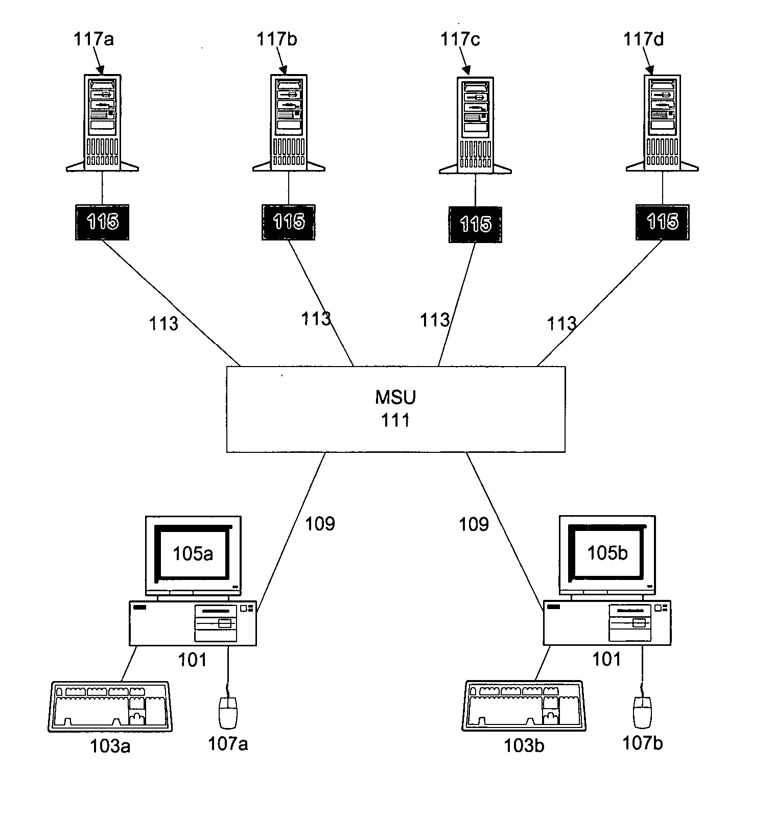
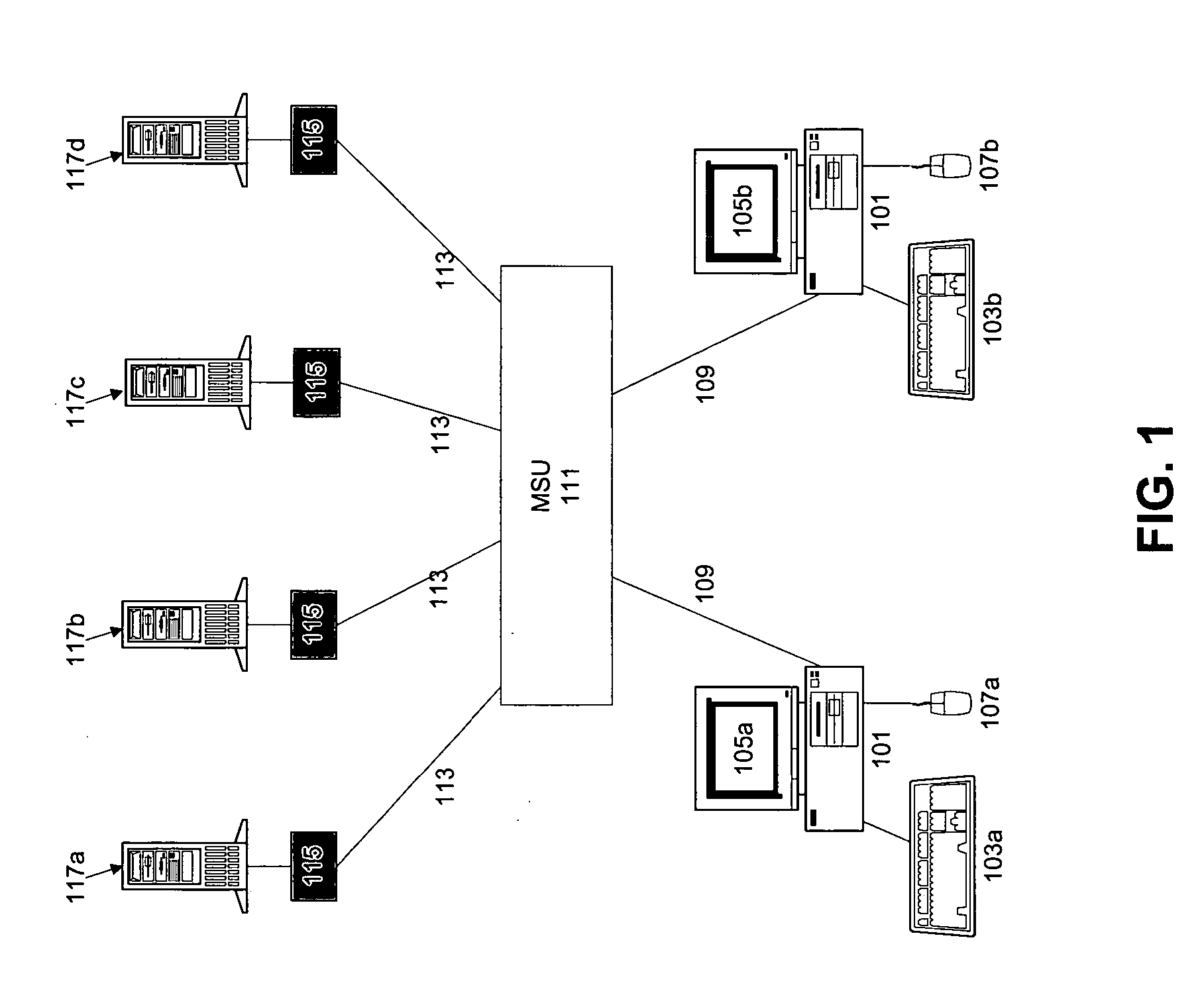
[0054] Referring first to FIG. 1, depicted is a conventional KVM switching system including user stations (“USTs”) 101 are shown with attached keyboards 103, video monitors 105, and cursor control devices 107. Each UST 101 is connected ...


PUM


Abstract

Disclosed is a system and method for correcting the separation of synchronized video signals resulting from transmission over wires of different lengths. Preferably, circuitry is used to inject a signal pulse along the red, green, and blue video signal transmission lines through a selectable delay circuit to a skew compensation circuit located at a user workstation. The skew compensation circuit sums the amplitudes of the received signal pulses and compares the result to a reference amplitude. This is repeated for each possible delay combination of the selectable delay circuits. The skew compensation circuit then determines the delay combination which produces a summed amplitude most closely matching the reference amplitude. This delay combination is implemented in the selectable delay circuits and normal video transmission is allowed to resume such that the red, green, and blue components of the video signal arrive at the video monitor at approximately the same time.

Description

FIELD OF THE INVENTION [0001] The present invention relates generally to KVM switches and the transmission of video signals over long distances. More specifically, the invention relates to a method and apparatus for the compensation or correction for the separation of synchronized signals transmitted over wires of different lengths. BACKGROUND OF THE INVENTION [0002] A typical computer setup includes a central processing device, a keyboard, a video monitor, a cursor control device (e.g., a mouse), and associated peripheral devices, such as printers, scanners, etc. The wires utilized to connect the keyboard, video monitor, and cursor control device to the computer are typically of a length of twelve feet or less. If the length of the wires is increased, there is often too much signal degradation for the keyboard, video monitor, and cursor control device to function properly. A number of systems exist to alleviate this problem, thus allowing a keyboard, video monitor, and cursor contr...

Claims


Application Information

Patent Timeline
Patent Type & Authority Applications(United States)
IPC IPC(8): G06F3/14H04N5/08H04N7/10H04N7/173H04N9/44H04N17/02
CPCG06F3/1454H04N5/08H04N17/02H04N7/17309H04N9/44H04N7/108
Inventor GLINSKI, LECHLIAW, YEE
Owner RIIP
Why Eureka
Try Eureka