
Saw

Inactive Publication Date: 2005-06-23
THE BOEING CO
View PDF11 Cites 9 Cited by
  • Summary
  • Abstract
  • Description
  • Claims
  • Application Information

AI Technical Summary

Benefits of technology

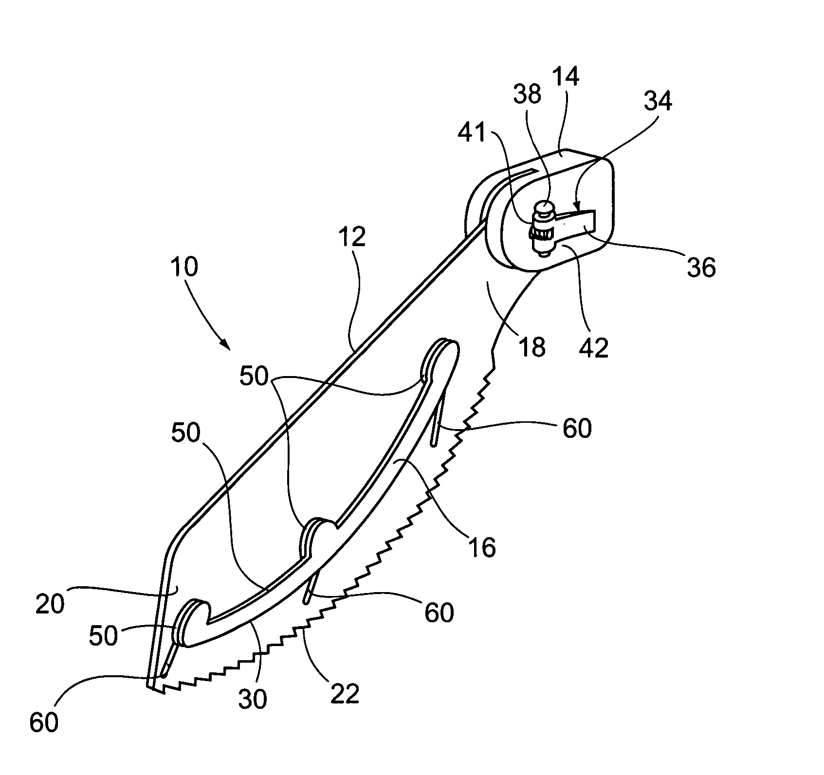
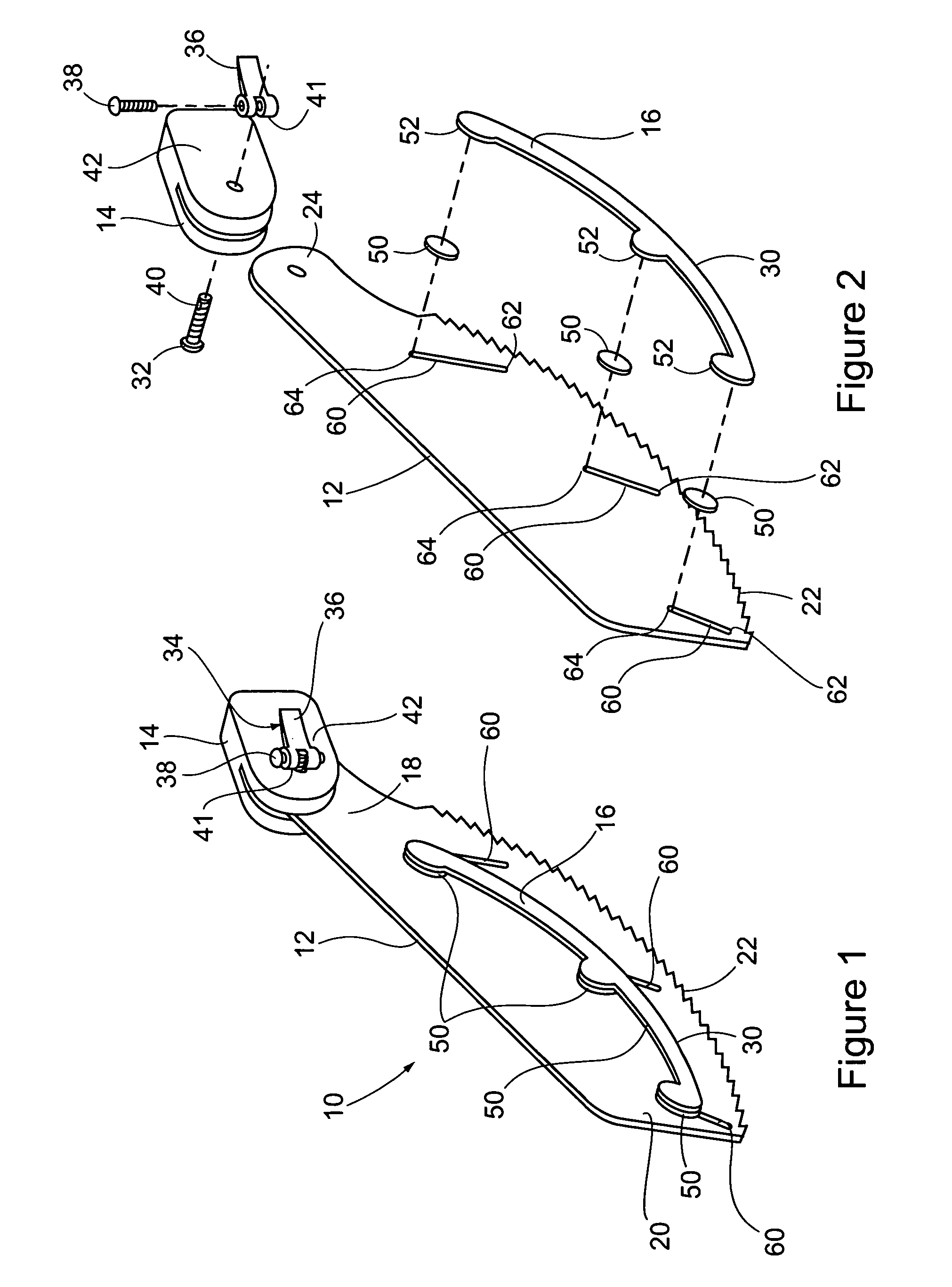
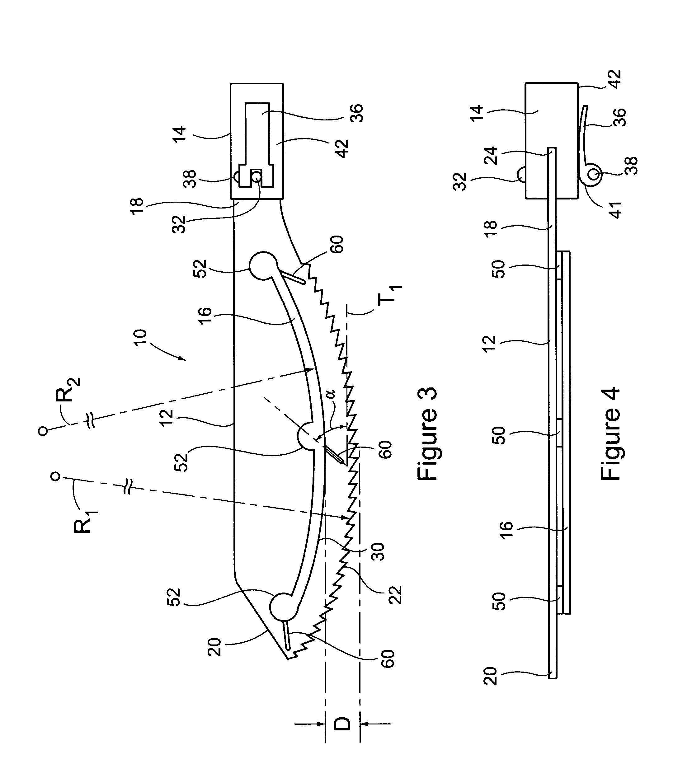
[0004] In general, a saw of the present invention comprises a generally planar saw blade, a handle, and a depth control guide. The saw blade has a proximal end and a distal end. The blade has an arcuate cutting edge extending along at least a portion of the saw blade between its proximal end and distal end. The blade has a shank portion adjacent its proximal end. The handle is adapted for hand-engagement by a user. The shank portion of the saw blade is pivotally connected to the handle in a manner to permit pivoting movement of the saw blade relative to the handle in a plane of the saw blade. The depth control guide comprises an arcuate depth control surface. The arcuate depth control surface is adapted for engagement with a surface of material being cut by the saw in a manner to control cutting depth. The arcuate depth control surface has a curvature that approximates a curvature of the arcuate cutting edge of the saw blade. The depth control guide is adjustably connected to the saw blade in a manner so that the distance between the arcuate depth control surface and the arcuate cutting edge of the blade can be selectively adjusted to achieve a desired cutting depth.
[0006] In still another aspect of the invention, a saw comprises a generally planar saw blade and a depth control guide. The saw blade is formed of a ferromagnetic material and has a cutting edge. The depth control guide has a depth control surface that is adapted for engagement with a surface of material being cut in a manner to control cutting depth. The depth control guide has at least one magnet. The depth control guide is adjustably connected to the saw blade via the magnet in a manner so that a distance between the depth control surface and the cutting edge of the saw blade can be selectively adjusted to achieve a desired cutting depth.

Problems solved by technology

Some amount of clearance is needed for the saw handle and the user's hand, which makes flush cuts of this kind difficult with a conventional saw.
Without sufficient flexibility of the blade, clearance needed for the saw handle or user's hand may not permit a sufficiently flush cut.
Known prior art flush-cutting blades have a generally straight cutting edge that is not suitable for starting cuts from within the plane of the material being cut.
The distal tip of the blade may be used to start a cut from within the plane of the material, but this is an awkward and difficult exercise and also results in premature wear of the teeth at end of the blade.
Known prior art flush-cutting saws also lack appropriate adjustability of the blades relative to the handles to allow access in tight locations.
However, such saws typically include some set or lateral inclination to the teeth, which makes them undesirable for use in a flush cutting operation.
Such saws also lack any means for accurately controlling the depth of the cut.

Method used


Image

  • Saw
  • Saw
  • Saw

Examples


Embodiment Construction

[0017] A saw of the present invention is represented in its entirety in FIG. 1 by the reference numeral 10. In general, the saw 10 comprises a saw blade 12, a handle 14 and a depth control guide 16. The saw blade 12 is generally planar and has a proximal end 18 and a distal end 20. Preferably, the blade 12 has an arcuate cutting edge 22, which extends along the saw blade between its proximal and distal ends. As best shown in FIG. 2, the proximal end 18 of the blade 12 includes a shank portion 24. The handle 14 is adapted for hand-engagement by a user (not shown). Preferably, the handle 14 and the shank portion 24 of the blade 12 are pivotally connected to one another in a manner to permit pivoting movement of the blade 12 relative to the handle 14 in a plane of the blade 12. The depth control guide 16 comprises an arcuate depth control surface 30, which is preferably generally perpendicular to the plane of the saw blade 12. As explained hereinafter, the arcuate depth control surface...


PUM

PropertyMeasurementUnit
Lengthaaaaaaaaaa
Forceaaaaaaaaaa
Angleaaaaaaaaaa

Abstract

A saw comprises a generally planar saw blade, a handle, and a depth control guide. The blade has an arcuate cutting edge. A shank portion of the saw blade is pivotally connected to the handle in a manner to permit pivoting movement of the saw blade relative to the handle in a plane of the saw blade. The depth control guide comprises an arcuate depth control surface, which is adapted for engagement with a surface of material being cut with the saw in a manner to control cutting depth. The arcuate depth control surface has a curvature that approximates a curvature of the arcuate cutting edge of the saw blade. The depth control guide is adjustably connected to the saw blade in a manner so that the distance between the arcuate depth control surface and the arcuate cutting edge of the blade can be selectively adjusted to achieve a desired cutting depth.

Description

BACKGROUND OF THE INVENTION [0001] The present invention relates to saws and, more particularly, to hand saws configured for making “flush cuts” and starter saws configured for starting cuts from within a plane of the material being cut. [0002] Saws capable of making “flush cuts” are known in the art. Such saws are capable of cutting through a protrusion that is perpendicular to a surface in manner so that the cut is “flush” to the surface. These saws are also useful for making cuts in locations having limited clearance, such as at a corner where the planes of two surfaces meet at a 90 degree angle. Some amount of clearance is needed for the saw handle and the user's hand, which makes flush cuts of this kind difficult with a conventional saw. Therefore, many saws designed for making flush cuts include saw blades that are of sufficient flexibility to permit the blade to be “flexed” so that a portion of the blade is parallel to and flush against a surface adjacent to the material bein...

Claims


Application Information

Patent Timeline
IPC IPC(8): B23D51/02B23D61/12B27B21/04B27B33/10
CPCB23D51/025B27B33/10B27B21/04B23D61/123
Inventor COLICH, JOSEPH M.
Owner THE BOEING CO
Learn More