Width-measuring method and surface texture measuring instrument

a technology of surface texture and measuring instrument, which is applied in the direction of mechanical measurement arrangement, mechanical roughness/irregularity measurement, instruments, etc., can solve the problems of difficult to be directly detected, difficult to collect data of a workpiece surface orthogonal to the pivoting direction (i.e. along the workpiece surface), and the width of recesses and treads of grooves and the like formed on the workpiece surface is difficult to be accurately measured, and achieves accurate and easy

Active Publication Date: 2005-06-23
MITUTOYO CORP
View PDF9 Cites 41 Cited by
  • Summary
  • Abstract
  • Description
  • Claims
  • Application Information

AI Technical Summary

Benefits of technology

[0027] According to the above aspect of the present invention, after scanning the outer right side of a column in Y-axis direction to obtain a measurement data by the detector of which coordinate value has been calibrated, the radius of the column can be immediately obtained based on the maximum value in the measurement data, which is doubled to calculate the diameter, thereby extremely easily measuring the width dimension.
[0028] As discussed above, according to the width-measuring method according to the present aspect of the invention, the inner diameter and outer d

Problems solved by technology

However, since the detectors of this type are single-axis detectors that detect irregularities in pivoting direction (i.e. Z-axis (vertical) direction in a surface roughness measuring instrument and contour measuring instrument and X-axis (front and back) direction in a roundness measuring instrument), though irregularities in the pivoting direction can be highly accurately detected, the data of a workpiece surface orthogonal to the pivoting direction (i.e. along the workpiece surface) is difficult to be collected.
For instance, characteristic-shape point such as workpiece edge (such edge is usually angled by ninety degrees) has been difficult to be directly detected and, especially, the width of recesses and treads of grooves and the like formed on the workpiece surface has been difficult to be accurately measured (for instance, see Japanese Patent

Method used


Image

  • Width-measuring method and surface texture measuring instrument
  • Width-measuring method and surface texture measuring instrument
  • Width-measuring method and surface texture measuring instrument

Examples


first embodiment

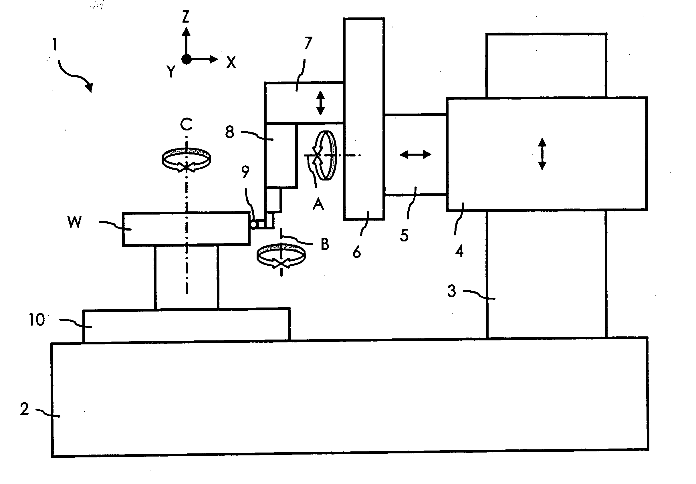
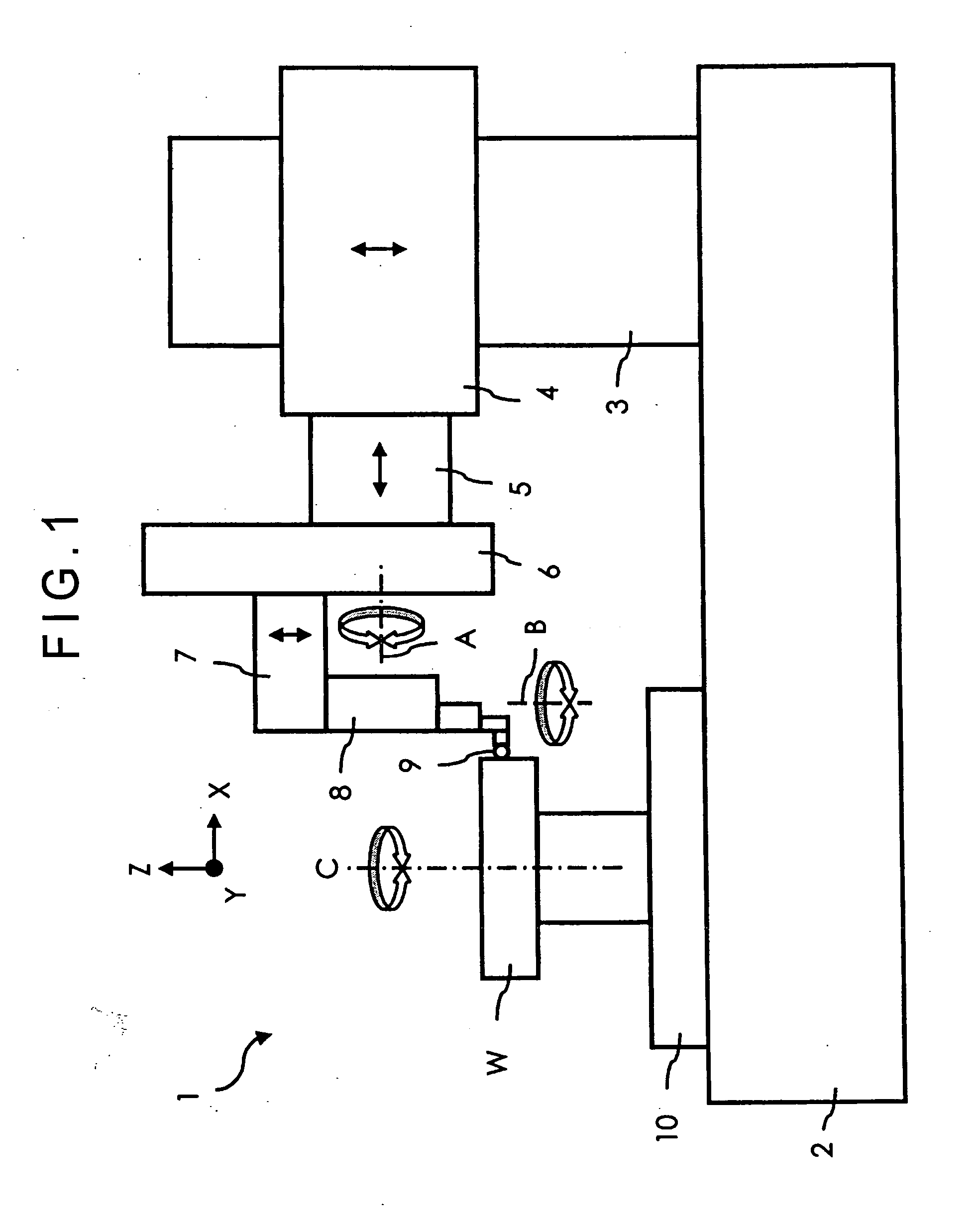
[0055]FIG. 1 shows a schematic arrangement of a roundness measuring instrument 1 according to a first embodiment of the present invention.

[0056] The roundness measuring instrument 1 shown in FIG. 1 has a base 2 and a rotary table 10 rotating around an axis C provided on an end of the upper side of the base 2, on which a workpiece W is rotatably mounted.

[0057] A column 3 is vertically installed on the other end of the upper side of the base 2. A Z-axis slider 4 is vertically (in Z-axis direction) slidable along the column 3. The Z-axis slider 4 holds an X-axis slider 5 in a manner slidable in right and left (i.e. in X-axis) direction.

[0058] A first arm 6 is provided on the X-axis slider 5 on the side of the rotary table 10 (leftward in the figure), the first arm 6 being rotatably held relative to the X-axis slider 5 around a center line A parallel to the X-axis. The first arm 6 holds an end of a second arm 7 in a manner slidable in vertical (as illustrated in FIG. 1) direction, i....

second embodiment

[0111] Next, a second embodiment of the present invention will be described below.

[0112] As shown in FIG. 16, a surface texture measuring instrument (roundness measuring instrument) used in the second embodiment is substantially identical with the instrument used in the first embodiment (FIGS. 1 and 2). Cross sections of a primary portion horizontally taken along line D-D in FIG. 16 are shown in FIGS. 17 and 18.

[0113] Unlike FIG. 1, the first arm 6 in FIG. 16 is rotated around the center line A to be horizontally held, so that the second arm 7 is capable of slide movement in horizontal (Y-axis) direction. In other words, in accordance with the slide movement of the second arm 7, the detector body 8 that is horizontally laid is advanced and retracted in Y-axis direction.

[0114] The workpiece W shown in FIG. 16 includes collars on top and bottom sides thereof. The diameter of the central column shaft sandwiched between the collars are to be measured in the second embodiment. Since s...

third embodiment

[0129] Next, a third embodiment according to the present invention will be described below.

[0130] Either the surface texture measuring instrument (roundness measuring instrument) used in the first embodiment (FIGS. 1 and 2) or that used in the second embodiment (FIG. 16) may be used in the third embodiment.

[0131] When the width is measured (diameter measurement) in accordance with the present invention using the roundness measuring instrument 1, the measurement process follows the specific steps of a flowchart shown in FIG. 21, which may be conducted by either one of the manual measurement and the automatic measurement by the part program.

[0132] Initially, the measurement process is started at S210.

[0133] Subsequently, the first arm 6 is held at an attitude shown in FIG. 17 and the calibration reference jig 20 is mounted on the rotary table 10. As shown in FIG. 22, the calibration reference jig 20 includes a vertical column 21, an inclined column 22 and a reference ball 23. The ...


PUM


Abstract

A surface texture measuring instrument has a rotary table on which a workpiece is rotatably mounted, a Z-axis slider capable of moving in a Z-axis direction parallel to a rotation axis of the rotary table, an X-axis slider that is held by the Z-axis slider and is advanceable and retractable in an X-axis direction orthogonal to the rotation axis, a first arm that is held by the X-axis slider and is rotatable around a center line parallel to the X-axis, a second arm that is held by the first arm and is advanceable and retractable in a direction orthogonal to the X-axis, and a detector held by the second arm to measure a surface texture of the workpiece.

Description

BACKGROUND OF THE INVENTION [0001] 1. Field of the Invention [0002] The present invention relates to a width measuring method using a surface texture measuring instrument. More specifically, it relates to a width-measuring method for measuring a width of a workpiece with a surface texture measuring instrument having a detector capable of changing measuring attitude thereof. [0003] 2. Description of Related Art [0004] Many of detectors used in a surface texture measuring instrument such as roundness measuring instrument, surface roughness measuring instrument and contour measuring instrument are provided with a contact piece attached to a tip end of a lever pivotably moved in a direction orthogonal to a surface of a workpiece, the detectors scanning the surface of the workpiece while keeping the contact piece in contact with the workpiece surface to collect measurement data, thereby analyzing the surface texture of the workpiece and / or measuring coordinates and dimension of the workp...

Claims


Application Information

Patent Timeline
IPC IPC(8): G01B5/08G01B5/20G01B5/28G01B7/04G01B7/34
CPCG01B5/08G01B5/28G01B5/201
Inventor KOJIMA, TSUKASASAKURADA, JUNJITAMAI, TOSHIYUKIMATSUMIYA, SADAYUKIKANO, TAKAFUMINOGUCHI, KAZUSHI
Owner MITUTOYO CORP
Why Eureka
Try Eureka