Capacitance z-axis accelerometer

a technology of capacitance and accelerometer, which is applied in the direction of speed/acceleration/shock measurement, measurement devices, instruments, etc., can solve the problems of difficult to prepare piezoelectric thin films of excellent properties without static characteristics, hardly compensated, and increased total volume, so as to reduce the size of the sensor, maximize the change of capacitance, and excellent acceleration sensitivity

Inactive Publication Date: 2005-06-23
SAMSUNG ELECTRO MECHANICS CO LTD
View PDF2 Cites 16 Cited by
  • Summary
  • Abstract
  • Description
  • Claims
  • Application Information

AI Technical Summary

Benefits of technology

[0016] It is an object of the present invention to provide a capacitance z-axis accelerometer which can be integrated together with x- and y-axis accelerometers into a single chip thereby reducing the size of a sensor, maximize the change of capacitance to have excellent acceleration sensitivity in the z-axial direction, reduce the amplification of a signal with an amplifier while decreasing the amplification of noise components contained in the signal to prevent the deterioration of the sensitivity of the sensor, and utilize an amplifier and a filter of low cost.

Problems solved by technology

Piezoelectric accelerometers are commercially retrogressing since it is difficult to prepare piezoelectric thin films of excellent properties without static characteristics.
Further, piezoresistant accelerometers show a wide range of characteristic change according to temperature variation, which is hardly compensated.
This structure has a problem that the total volume increases because the vertical z-axis accelerometer 1 increases the overall height occupying a large space together with the x- and y-axis accelerometers.
However, this also complicates the overall structure of the accelerometer and raises fabrication cost as well.
Furthermore, because noise components in an input signal are also amplified together, a higher amplification rate generates an output signal containing more noise and nonlinear components thereby further deteriorating the performance of the accelerometer.

Method used


Image

  • Capacitance z-axis accelerometer
  • Capacitance z-axis accelerometer
  • Capacitance z-axis accelerometer

Examples


Embodiment Construction

[0047] Preferred embodiments of the present invention will now be described in detail with reference to the accompanying drawings.

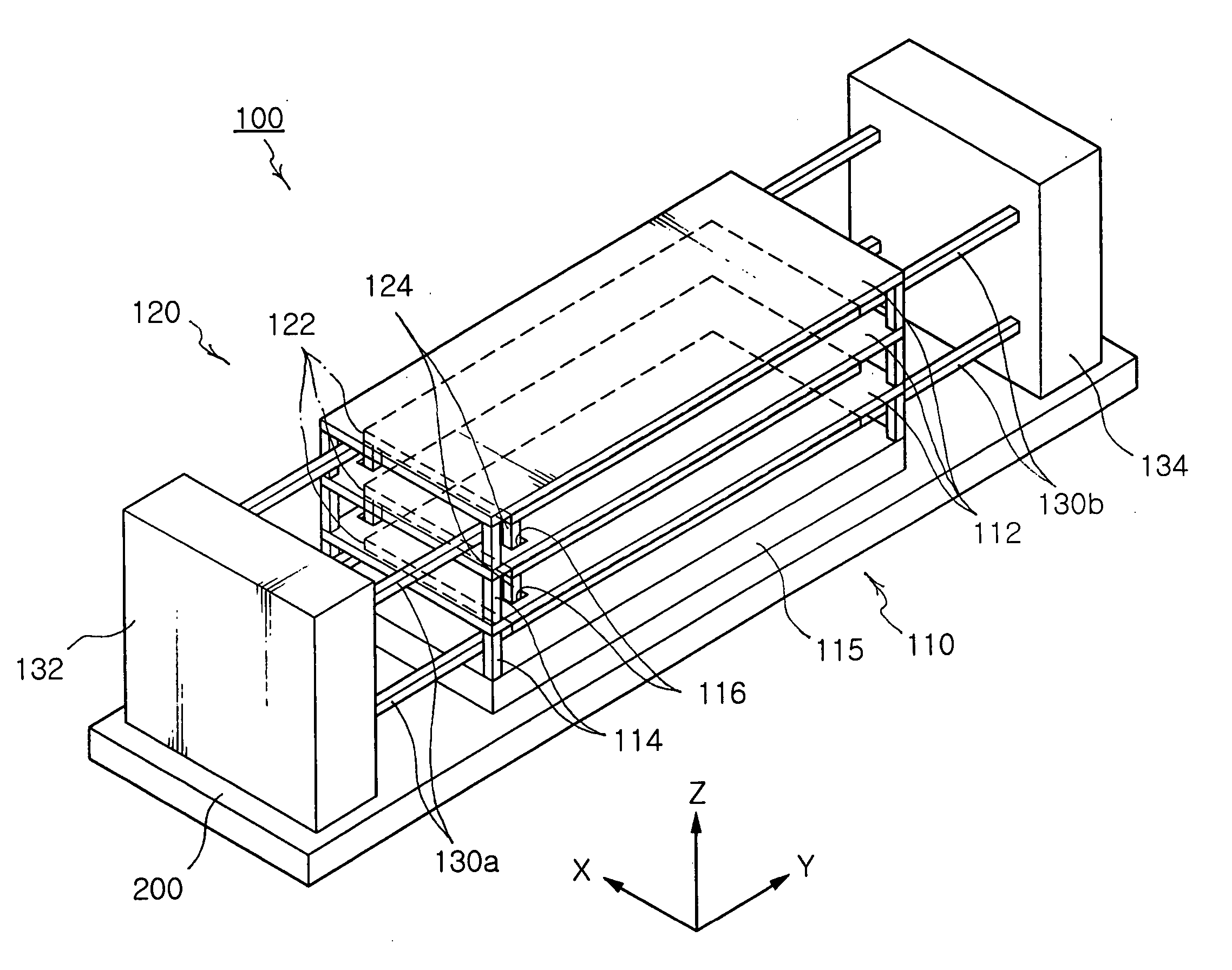
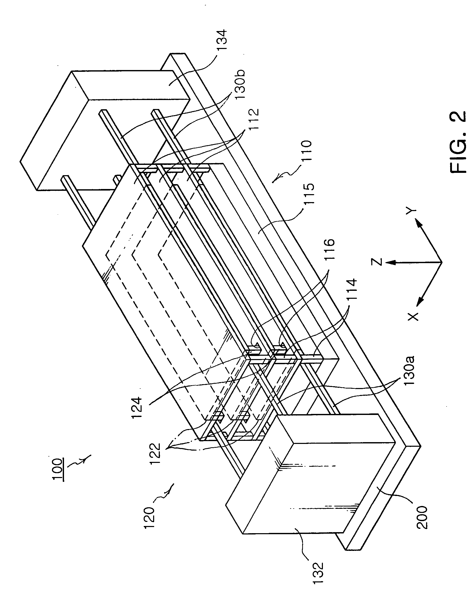
[0048]FIG. 2 is a perspective view of a capacitance z-axis accelerometer according to the invention, FIG. 3A is a plan view of the capacitance z-axis accelerometer in FIG. 2, FIG. 3B is a side elevation view of the capacitance z-axis accelerometer in FIG. 2, FIG. 3C is a longitudinal sectional view of the capacitance z-axis accelerometer in FIG. 2 taken along a line A-A′, FIG. 4A is a plan view taken along a line B-B′ in FIG. 3B, and FIG. 4B is a plan view taken along a line C-C′ in FIG. 3B.

[0049] As shown in FIGS. 2 to 4B, an accelerometer 100 of the invention has a plurality of electrode plates placed one above another to achieve a high sensitivity with respect to z-axial acceleration as well as a small installation height so that the accelerator 100 can be integrated together with x- and y-axis accelerometers into one chip. The accelerometer 100 incl...


PUM


Abstract

Disclosed is a capacitance accelerometer comprising a fixed electrode, a movable electrode and support beams. The fixed electrode has rectangular fixed electrode plates arranged parallel with a top surface of an insulation board. The fixed electrode plates are placed one above another via posts, and arranged on an electrode-fixing section of the insulation board. The movable electrode has rectangular movable electrode plates alternating with the fixed electrode plates. The movable electrode plates are placed one above another via connector posts placed within guide holes perforated through the fixed electrode plates. The support beams connect the movable electrode with beam-fixing sections to elastically support the movable electrode. The capacitance z-axis accelerometer can be integrated together with x- and y-axis accelerometers into a single chip, maximize the change of capacitance to achieve excellent acceleration sensitivity, and utilize an amplifier and a filter of low cost.

Description

BACKGROUND OF THE INVENTION [0001] 1. Field of the Invention [0002] The present invention relates to a capacitance accelerometer, and more particularly, a capacitance z-axis accelerometer which can be integrated together with x- and y-axis accelerometers into a single chip and maximize the change of capacitance to achieve excellent acceleration sensitivity in the z-axial direction as well as utilize an amplifier and a filter of low cost. [0003] 2. Description of the Related Art [0004] An accelerometer is known as a Micro Electro Mechanical System (MEMS) device. MEMS devices indicate microscale mechanical devices that are electrically controlled and measured, in which the MEMS is a technique for fabricating mechanical and electrical devices through the semiconductor process. [0005] Various accelerometers capable of measuring acceleration are being currently developed, and adopted in vehicle air bag systems, Anti-lock Brake Systems (ABS) and general vibrometers. The accelerometers are...

Claims


Application Information

Patent Timeline
Patent Type & Authority Applications(United States)
IPC IPC(8): G01P15/125
CPCG01P15/125
Inventor PARK, HO JOONCHAE, KYOUNG SOO
Owner SAMSUNG ELECTRO MECHANICS CO LTD
Why Eureka
Try Eureka