
Traversing circular saw

a circular saw and saw blade technology, applied in the field of circular saws, can solve the problems of common chain breakage, chain/bar saw type cannot be used in northern locations on frozen trees, chain/bar saw types are easily bound or stalled, etc., and achieve the effect of increasing the initial revolution per minute (rpm) of the saw blade, maximizing the cradle width, and increasing the initial pressur

Inactive Publication Date: 2005-06-23
MAINS SAW
View PDF4 Cites 9 Cited by
  • Summary
  • Abstract
  • Description
  • Claims
  • Application Information

AI Technical Summary

Benefits of technology

[0014] It is an object of this invention to provide a circular saw which can be moved transversely across the cradle, such that the cradle width can be maximized. It is a further object to provide such a saw in which the blade is moved in a non-jointed and controlled manner, whereby shifting logs will not bind and stop the blade's rotation.
[0016] It is yet another object of the invention to provide a circular saw which advantageously has increased initial rotational speed, or rpms, at the time of engagement so that the rpms are maximized as the saw blade is extended across the cradle to cut the logs.

Problems solved by technology

The circular saws are more powerful than the chain / bar saw type, and the chain saw type cannot be used in northern locations on frozen trees.
Additionally, the chain / bar saw types are easily bound or stalled by the logs and breakage of the chain is common.
A primary drawback of the first type of circular saw described, which only pivots down onto the logs to be cut, is that the width of the cradle is limited by the size of the blade diameter.
Because the cradle size is limited, the amount of wood able to be cut with each pass is also limited.
Because of this mechanism, the saw blade is readily subject to binding and stoppage, since the multi-jointed arm is not strong enough to counter any shifting of logs against the blade.
This forces the blade off-line and results in stoppage, requiring the operator to retract the blade and start over.
However, the extra pivoting step required by this device can increase the time involved for cutting the logs.
In addition, this device is more complex and requires additional parts and engineering for accomplishing the pivoting step.

Method used


Image

  • Traversing circular saw
  • Traversing circular saw
  • Traversing circular saw

Examples


Embodiment Construction

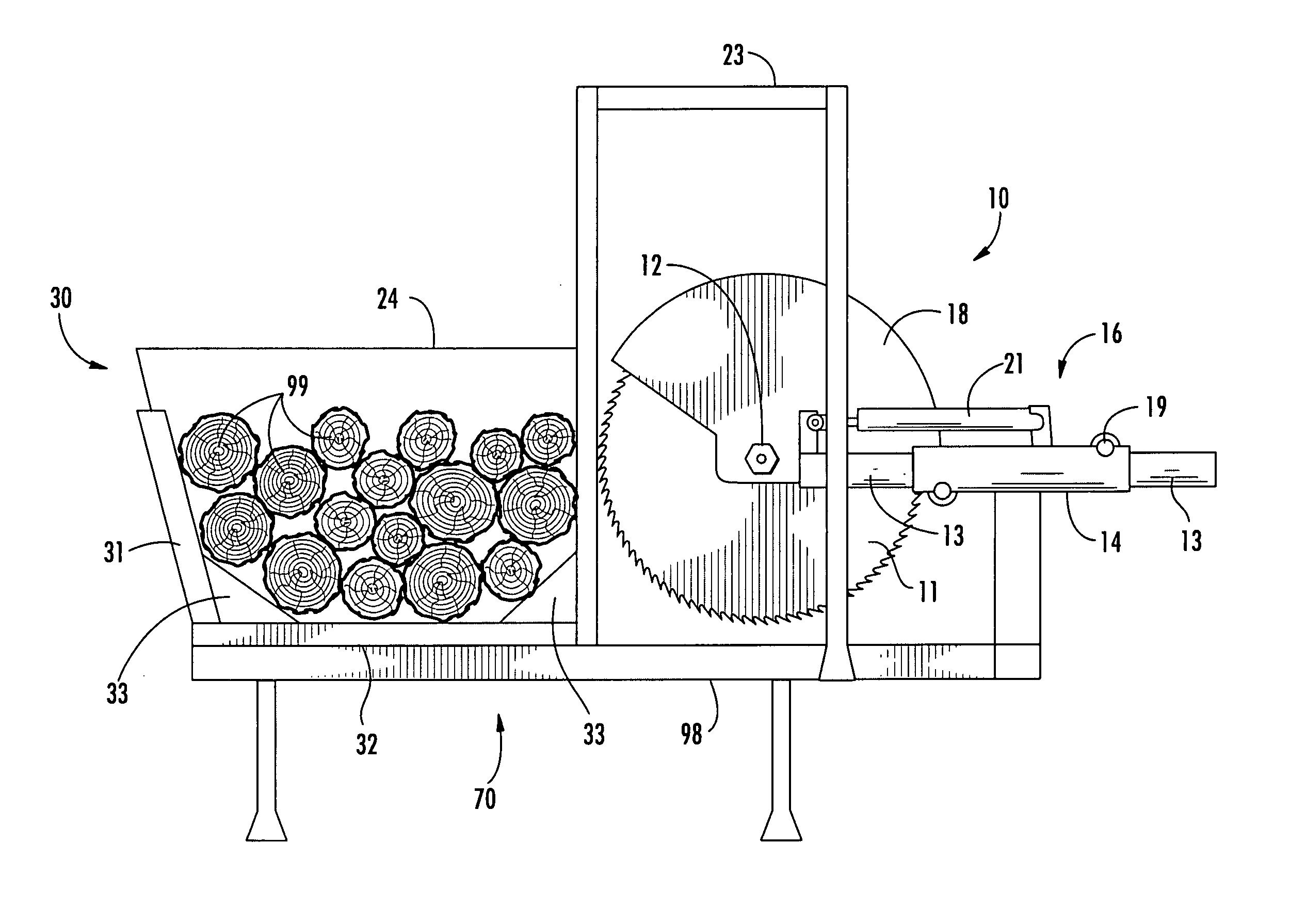
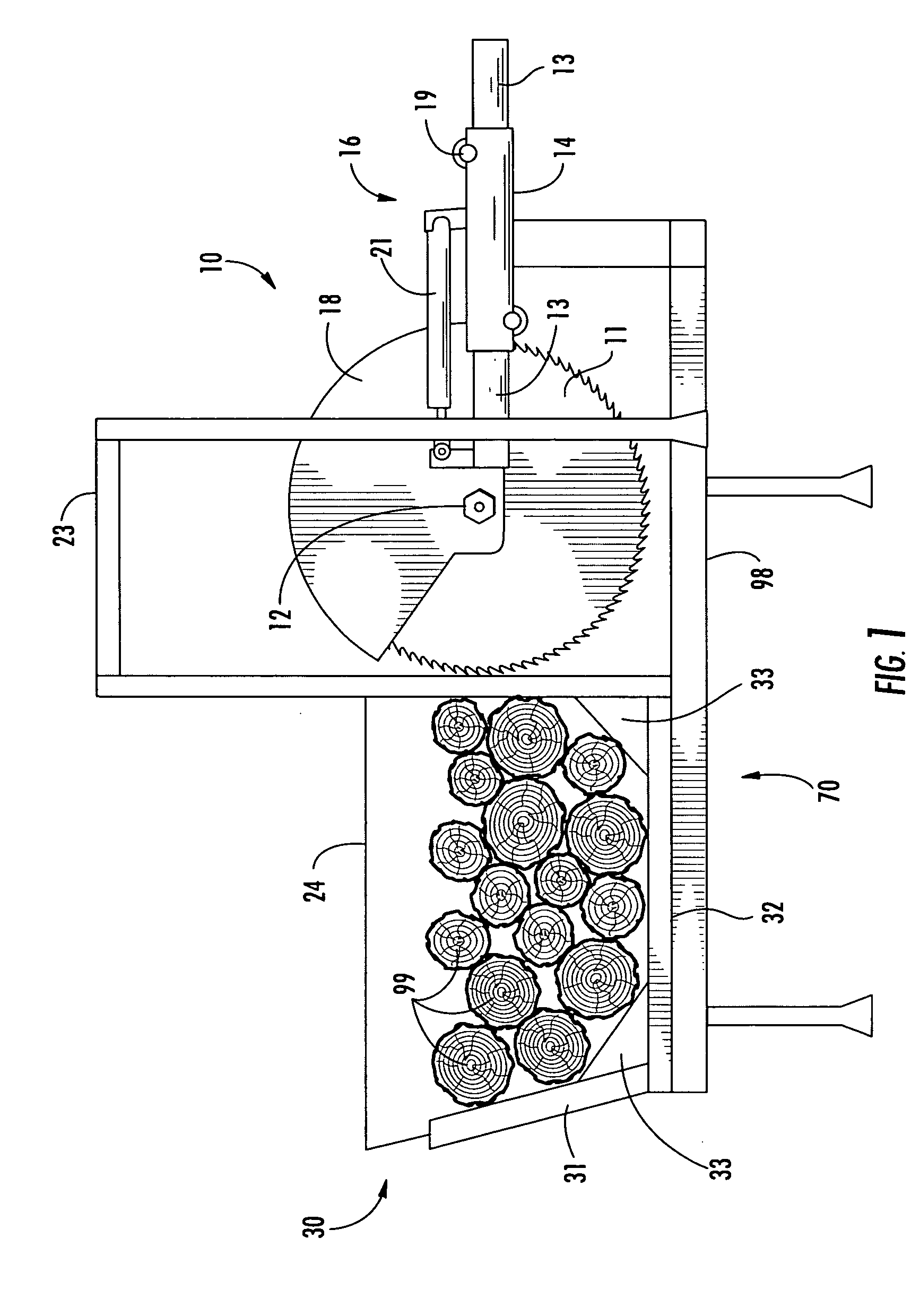
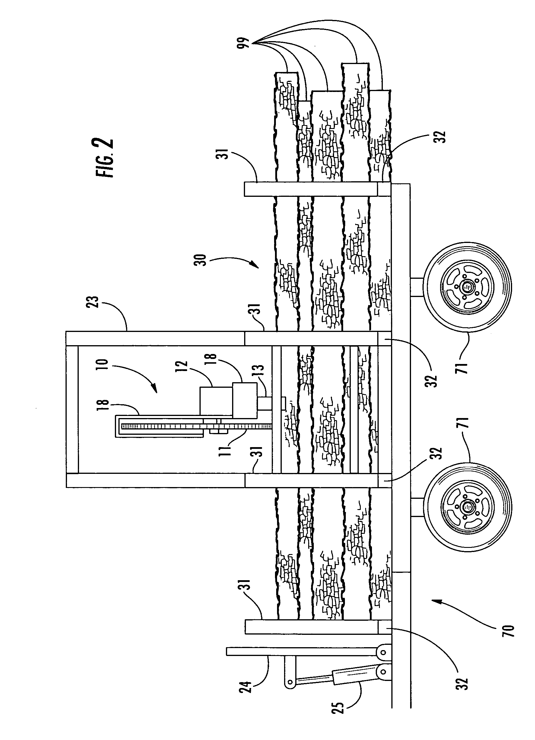
[0025] With reference to the figures, the invention will now be described in detail, providing the preferred embodiment and best mode. As shown in FIGS. 1 and 2, the invention is an apparatus for cutting logs 99 into shorter segments for ease in handling, packing and transportation, comprising in general a circular saw blade assembly 10 mounted onto or connected to cradle means 30 for receiving the logs 99. Preferably, the apparatus is mounted on or incorporates a trailer 70, optionally having wheels (shown in FIG. 2) to facilitate moving the entire unit to any desired location.

[0026] Cradle means 30 is a receiving and holding means to retain the logs 99 in position during the cutting operation. Cradle means 30 also retains the cut segments of the logs 99 so that they can be removed by a grapple. Cradle means 30 extends longitudinally, such that the logs 99 are loaded lengthwise parallel to the longitudinal axis of the cradle means 30. Cradle means 30 can be constructed in various ...


PUM

PropertyMeasurementUnit
lengthaaaaaaaaaa
lengthaaaaaaaaaa
diameteraaaaaaaaaa

Abstract

A traversing circular saw device having a saw blade assembly mounted onto a cradle which can receive a number of logs to be cut into sections. The saw blade assembly includes a circular saw blade mounted onto an extension arm which is contained within an arm sleeve. The width of the cradle is greater than the diameter of the saw blade. The saw blade is extended across the cradle by a piston. One embodiment of the invention includes a charge accumulator for the hydraulic system which can time-delay engagement of the extension means. The system can also include a flow control valve for varying the time delay of the charge accumulator.

Description

BACKGROUND OF THE INVENTION [0001] This invention relates generally to the field of circular saws, and more particularly to the field of circular saws which move relative to the work piece being cut. Even more particularly, the invention relates to large circular saws moved hydraulically in a traversing motion relative to an optional workplace receiving cradle, such as saws used in the logging industry to cut trees into short wood lengths. [0002] There are numerous steps in bringing a tree from the forest to a mill for final processing into lumber, pulp, etc. Each tree is felled, delimbed and transported by truck to the mill. For some uses the logs are cut into short sections, usually from 4 to 8 feet in length. “Cutting short wood”, as it is known, may occur in the field prior to loading on the trucks, at intermediary wood yards for loading the wood onto trucks or rail cars, or at the mill itself. For increased speed, a number of logs (typically 2-20) are cut in a single pass with ...

Claims


Application Information

Patent Timeline
Patent Type & Authority Applications(United States)
IPC IPC(8): B23D47/10B27B5/10B27B5/18B27B27/02B27B27/10F15B21/10
CPCB23D47/10B27B5/10F15B21/10B27B27/02B27B27/10B27B5/187Y10T83/9372
Inventor MAINS, DOUG
Owner MAINS SAW
Learn More