

Electric oven with door cooling structure
a technology of electric oven and cooling structure, which is applied in the field of electric ovens, can solve the problems of deteriorating user safety, affecting the safety of users, and users may inadvertently get burned, so as to prevent damage and uniform cooling
- Summary
- Abstract
- Description
- Claims
- Application Information
AI Technical Summary
Benefits of technology
Problems solved by technology
Method used
Image

Examples
first embodiment
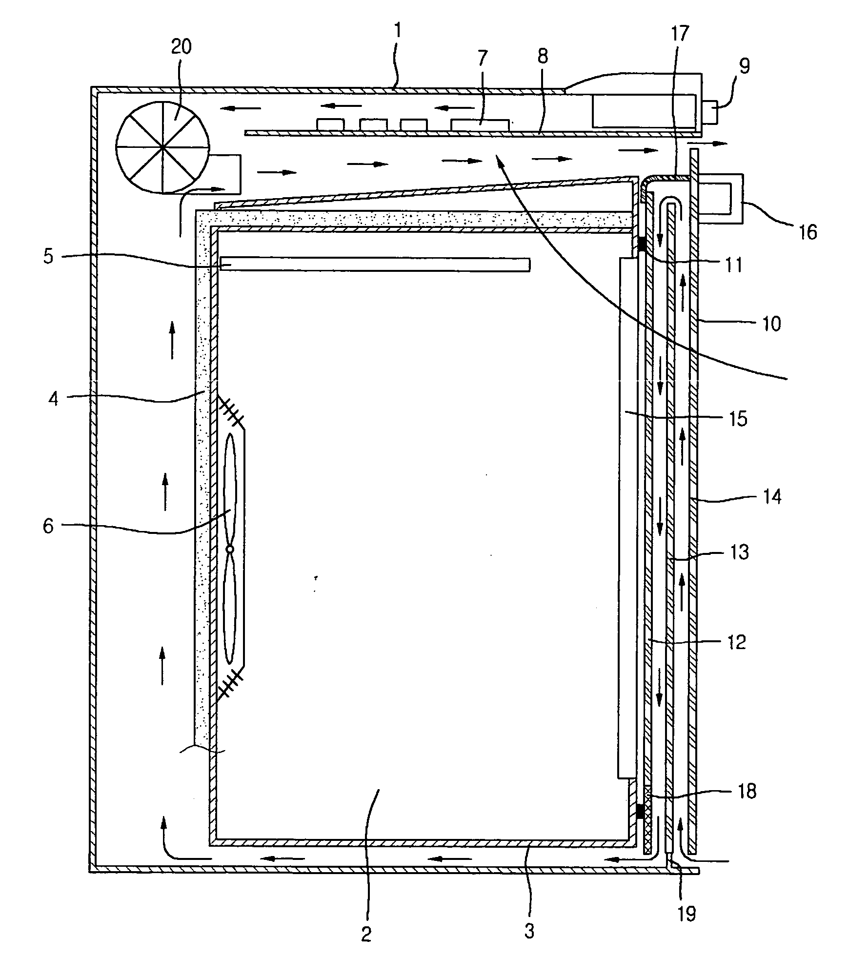
[0030]FIG. 1 shows an electric oven with a door cooling structure according to a first embodiment of the present invention.
[0031] Referring to FIG. 1, an electric oven comprises a case 1, a cavity 2 defined by a cavity wall 3 disposed in the case, an insulating layer 4 enclosing an outer surface of the cavity wall 3, and a door 10 for selectively opening / closing a front opening 15 of the cavity 2.
[0032] The electric oven further comprises a front operation panel 9, an electric unit 7 required for operating the electric oven, and a blower fan 20 for forcedly flowing air used for cooling the electric unit 7.
[0033] The door 10 comprises a door frame 18, inner, intermediate and outer panels 12, 13 and 14 disposed in the door frame 18, a sealing portion 11 formed on a portion of the door 10, which contacts the cavity wall 3 to insulate an inside of the cavity 2, a door cover 17 for sealing an upper portion of the door 10, and a door handle 16.
[0034] As a heat source for heating the i...
second embodiment
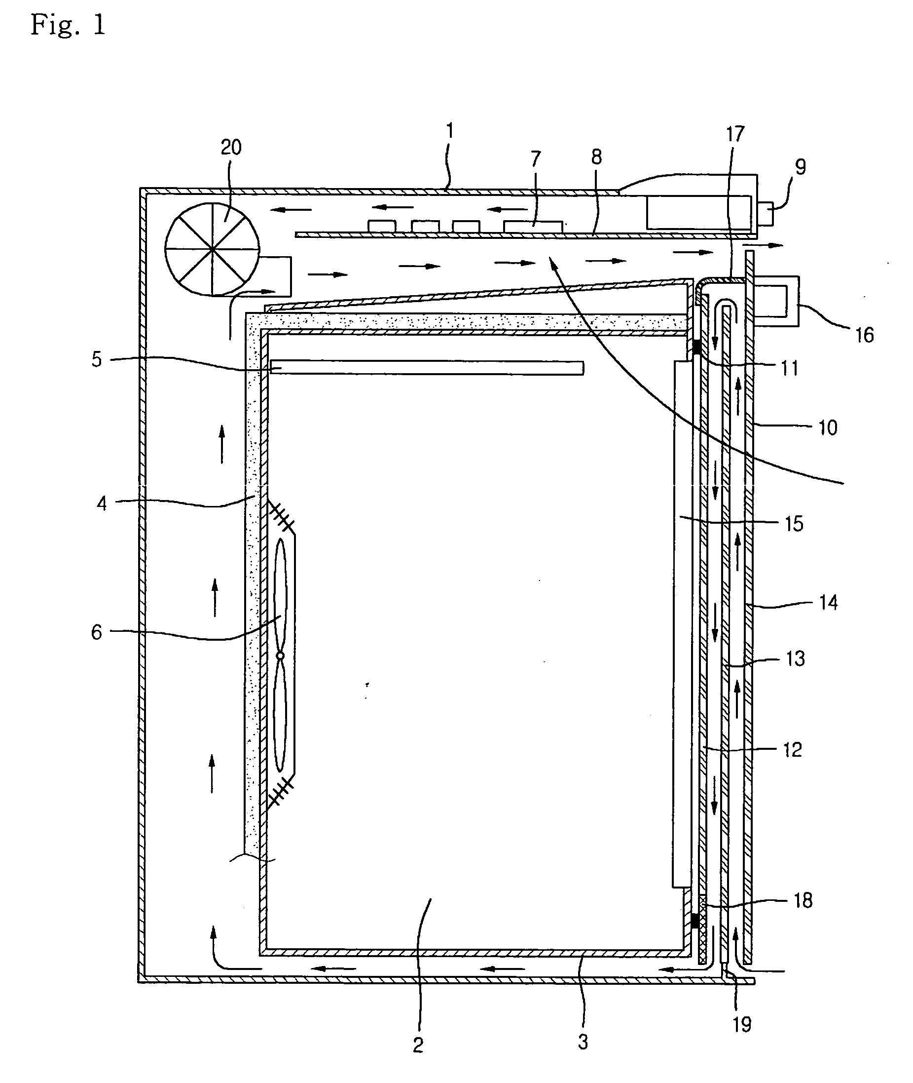
[0041]FIG. 2 shows an electric oven with a door cooling structure according to a second embodiment of the present invention. In this embodiment, a description of identical portions to those of the first embodiment will not be described, but only a different will be described hereinafter.
[0042] Referring to FIG. 2, in order to enhance the door cooling efficiency, a door cooling fan 60 is further provided between a lower portion of a cavity wall 33 and a case 31. Preferably, the cooling fan 60 is provided on a front portion of a gap between the cavity wall 33 and the case 31 so that enhanced negative pressure can be applied to gaps between panels 42, 43 and 44. In addition, an exhaust side of the cooling fan 60 is designed to be directed rearward of the oven so that a strong, speedy wind can be generated between the cavity wall 33 and the case 31.
[0043] As described above, since the enhanced negative pressure is applied to the inside of the door, the more strong, speedy wind is appl...
third embodiment
[0045]FIGS. 3 through 7 show an electric oven with a door cooling structure according to a third embodiment of the present invention.
[0046] This embodiment is identical to the second embodiment except for a method and structure for controlling airflow for cooling the door.
[0047] Referring first to FIG. 3, in order to enhance the door cooling efficiency, a door cooling fan 90 is disposed between a cavity wall 63 and a case 61 and an airflow guide 88 for exhausting air from the cooling fan 90 to an exterior side is provided. Preferably, the cooling fan 90 is provided on a front portion of a gap defined between the cavity wall 63 and the case 61 so that enhanced negative pressure can be applied to gaps between the panels 72, 73 and 74. In addition, an exhaust side of the cooling fan 90 is designed to be directed rearward of the oven so that a strong, speedy wind can be generated between the cavity wall 63 and the case 61.
[0048] The air used for cooling the inside of the door 70 is e...
PUM
 Abstract
Description
Claims
Application Information