
Speaker box for use in back-load horn

Inactive Publication Date: 2005-06-23
HASEGAWA YASUEI
View PDF15 Cites 15 Cited by
  • Summary
  • Abstract
  • Description
  • Claims
  • Application Information

AI Technical Summary

Benefits of technology

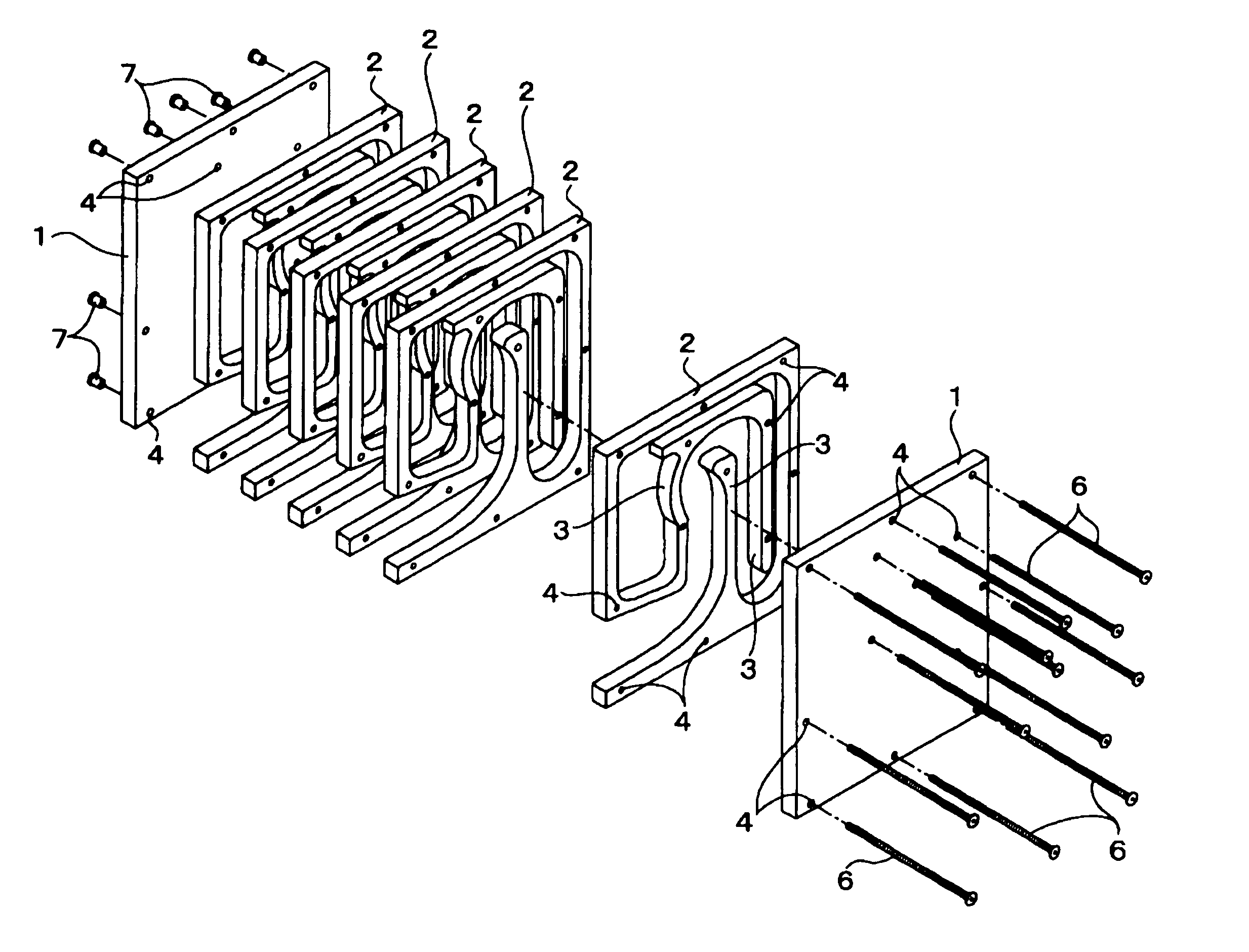
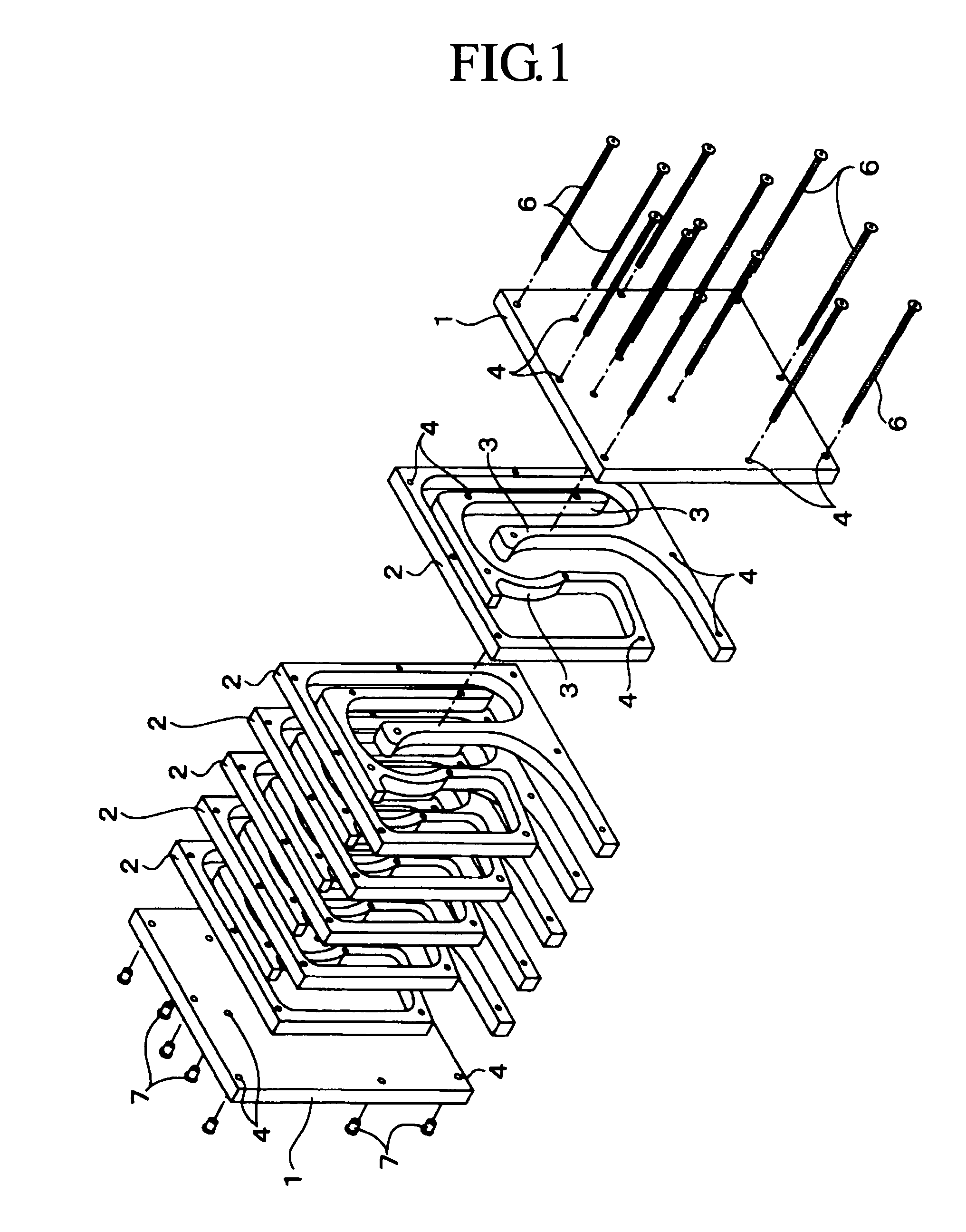
[0009] In this invention, therefore, a speaker box furnished inside the main body thereof with a highly accurately curved sound channel can be obtained simply by performing an economically inexpensive NC (numerical control) machining on a plurality of intermediate plates interposed between two lateral plates, thereby forming therein curved walls jointly defining a sound channel, and subsequently joining the intermediate plates and the two lateral plates in a laminated form and securing them with bolts. Thus, anyone can manufacture this speaker box with ease. Particularly, the structure mentioned above can promise provision of highly mass-producible and inexpensive speaker boxes.
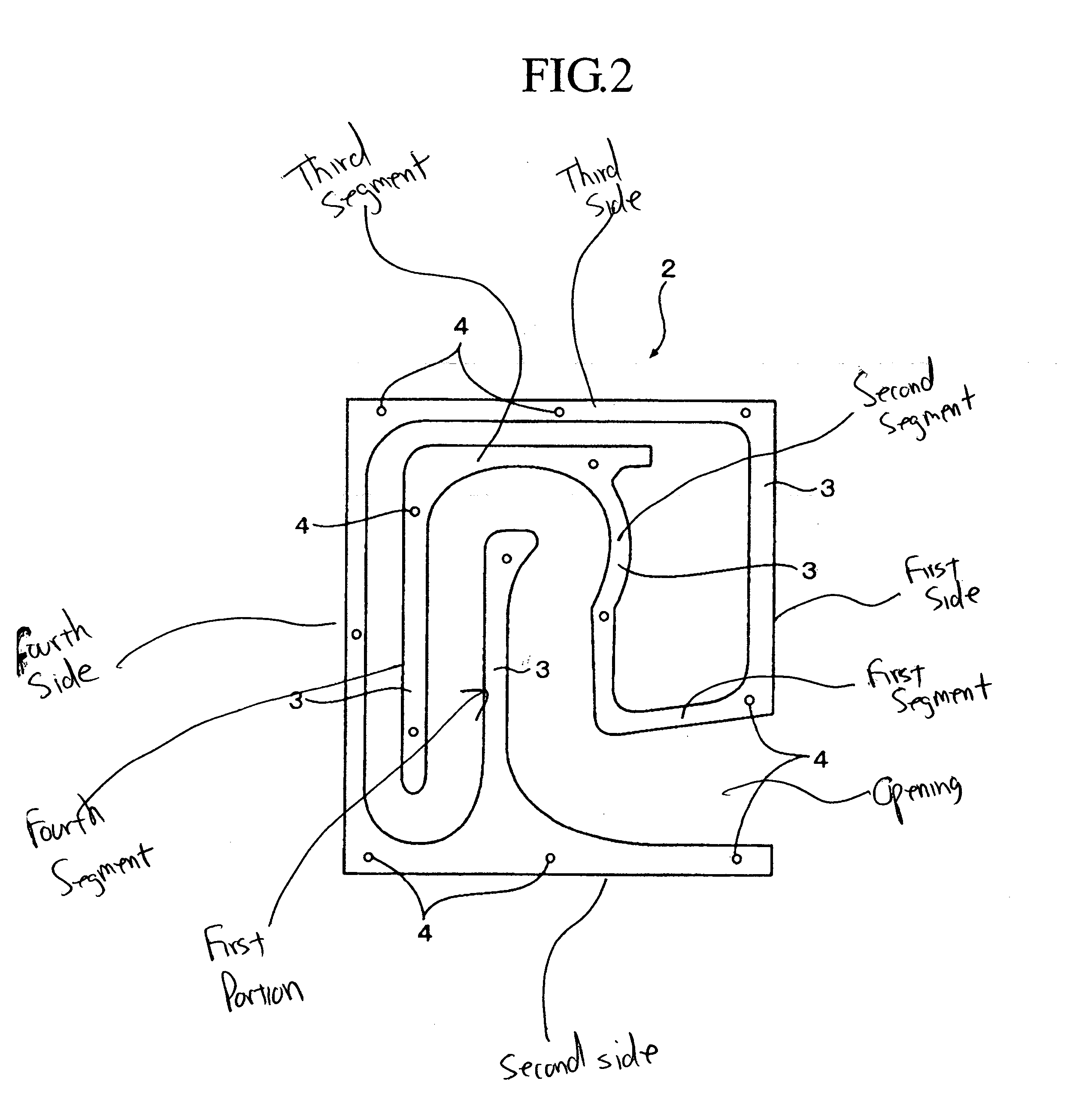
[0010] Securement with bolts provides a perfect solution to a problem of sound leakage because this prevents individual curved walls from including unnecessary gaps therebetween. Variation of sound can also be enjoyed by properly deciding a number of intermediate plates. Furthermore, turbulence of sound reflection and air current can be allayed, and turbidity of sound can be eliminated because corner parts in the sound channel may be finished in curvilinear shapes, and diverging parts in the sound channel may be finished in curvilinear shapes, designed in advance by calculation.

Problems solved by technology

Since the speaker box is required to form therein a long sound channel curved intricately with an object of amplifying low sound, formation of this sound channel imposes various restrictions on tasks of design and manufacture.
A conventional speaker box of this construction, however, has proved unsuitable for mass production because it has required work of cutting numerous wood plate materials into pieces of necessary dimensions, and manually assembling these cut pieces with strict accuracy and automatically rendered tasks of design and manufacture very irksome.
Notwithstanding that the sound channel for the back-load horn is inherently required to ideally be of an intricately curved long curvilinear shape, it is virtually impossible to form an intricately curved sound channel by merely assembling rectangular plate materials.
Thus, a strong point of the back-load horn cannot be fully satisfactorily utilized.
Moreover, it is not easy for the sound channel to acquire a closed structure, no matter how heedfully the cut pieces of plate materials may be assembled.
In consequence of this difficulty, a produced speaker box has a possibility of inducing leakage of sound.

Method used


Image

  • Speaker box for use in back-load horn
  • Speaker box for use in back-load horn
  • Speaker box for use in back-load horn

Examples


Embodiment Construction

[0015] Now, this invention will be described in detail below with reference to a preferred embodiment thereof illustrated in the drawings. A speaker box for use in a back-load horn according to the embodiment is unexceptionally formed by assembling wood plate materials, such as wood fiberboards (MDF boards=medium-density fiber boards). The speaker box differs from a conventional speaker box in that a main body of the speaker box is finished in a laminated form.

[0016] To be more specific, the speaker box according to the embodiment of this invention comprises two lateral plates 1, destined to form lateral walls of the main body of the speaker box, and a plurality of intermediate plates 2 interposed between the two lateral plates 1 as illustrated in FIG. 1. The speaker box is characterized by forming equal curved walls 3 destined to define jointly a sound channel coincidently in the intermediate plates 2, and joining these intermediate plates 2 and the two lateral plates 1 in a lamin...


PUM


Abstract

A speaker box that is furnished inside a main body thereof with a curved sound channel, and used in a back-load horn, adopts a structure comprising two lateral plates and a plurality of intermediate plates interposed between the lateral plates, which plates are joined in a laminated form and secured with bolts. The intermediate plates individually have curved walls that jointly define a sound channel inside the main body of the speaker box.

Description

BACKGROUND OF THE INVENTION [0001] 1. Field of the Invention [0002] This invention relates to a speaker box for use in a back-load horn furnished in an interior of a main body thereof with a curved sound channel. [0003] 2. Description of Related Art [0004] Among enthusiasts for audio, a back-load horn system has been attracting great attention because the system, even though used in a small speaker unit, is characterized by enabling depth of body of a low tone zone of sound to be exalted by allowing high sound and intermediate sound emanating from a front surface of the speaker unit to be directly radiated and causing the low sound emanating backward from the system to be passed through a long sound channel and reproduced orthodoxly. [0005] Various attempts directed toward development of a speaker box for use in the back-load horn system of this principle have been underway. Since the speaker box is required to form therein a long sound channel curved intricately with an object of a...

Claims


Application Information

Patent Timeline
IPC IPC(8): H04R1/28H04R31/00
CPCH04R31/00H04R1/2865
Inventor HASEGAWA, YASUEI
Owner HASEGAWA YASUEI
Learn More