This helps you quickly interpret patents by identifying the three key elements:
Problems solved by technology
Method used
Benefits of technology
Benefits of technology
This patent describes a reinforcement plate used in a haul truck's lining element. By placing cut-out openings in the reinforcement plate, the weight of the lining element is reduced while keeping it in a desired shape. The reinforcement plate's bent edges help keep the lining element in place, and the cut-out openings are shaped as rectilinear polygons for easy manufacturing. The reinforcement plate may also have an outer frame for added stiffness. This design allows for a lighter haul truck with a larger payload and better grip on the lining element.
Problems solved by technology
Rubber tends to shrink after the manufacturing process, which otherwise would cause the plate to be bent out of shape.
Method used
Image
Click on the blue label to locate the original text in one second.
Reading with bidirectional positioning of images and text.
Examples
first embodiment
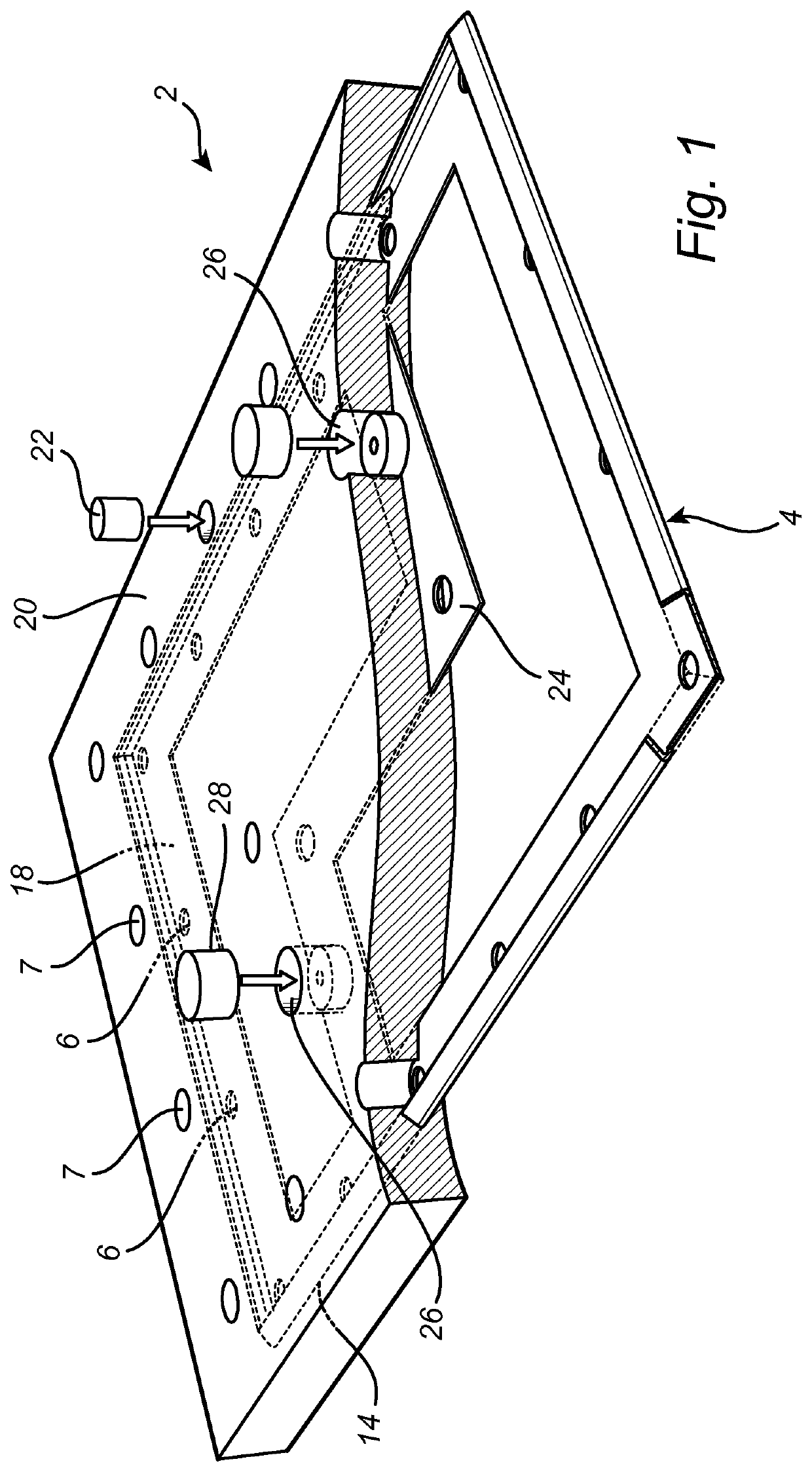
[0046]In the first embodiment, as shown in FIG. 1, a strip portion 24 consists of three orthogonal linear strip segments. Two lifting structures 16 are located on the strip portion 24. Such an arrangement thus allows for a relatively central location of the lifting structures 16 and / or mounting holes 6.
second embodiment
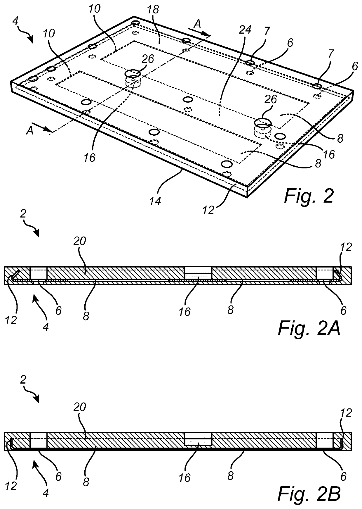
[0047]FIG. 2 shows a reinforcement plate 4 which is part of a lining element 2. according to a A linear strip section 24 here extends between the two short sides of the frame 18, thus forming two elongate, rectangular cut-out openings 8.
[0048]FIG. 2A shows a cross sectional view of the same reinforcement plate 4 as in FIG. 2, along the cross-section A-A as indicated in FIG. 2, and as well the rubber coating 20. The bent edge 12 of the reinforcement plate 4 grips into the rubber, keeping the rubber in place.
[0049]FIG. 2B shows a cross sectional view of an alternative embodiment to the second embodiment of FIGS. 2 and 2A. This embodiment is identical to the second embodiment, with the exception that the edges 12 of the reinforcement plate 4 are bent 90 degrees (also cf. FIG. 5d).
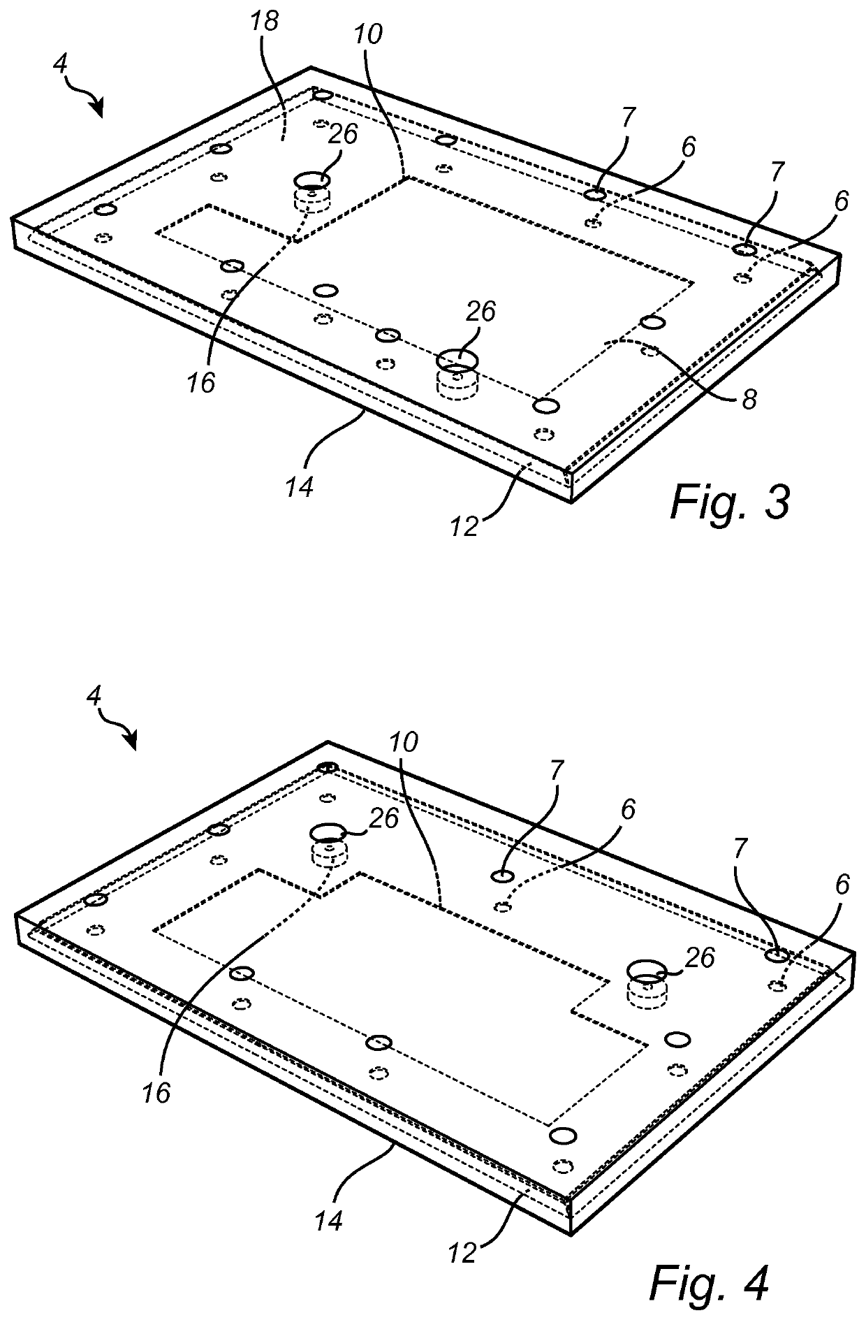
[0050]FIG. 3 shows a lining element 2 with a reinforcement plate 4 according to a third embodiment. Mounting holes 6 and a bent outer edge 12 are present as for the second embodiment shown in FIG. 2. Contrary...
fourth embodiment
[0051]FIG. 4 shows a reinforcement plate 4 according to a Mounting holes 6 and a bent outer edge 12 are present as before. Here, the single cut-out opening 8 has an orthogonal octagon shape allowing for a relatively central placement of two lifting elements 16.
[0052]FIGS. 5a and 5b show detailed cross sections of how the edge 12 of the reinforcement plate 4 bends. The bend is preferably more than 90 degrees, and less than 180 degrees, and is thus V-shaped as in FIG. 5b or almost U-shaped as in FIG. 5a, to properly grip the rubber coating. This inward bend prevents the rubber to be cut by the edge upon loading impact.
[0053]The bend may also be 180 degrees as shown in FIG. 5c. It may then have an overlapping section 30 with the unbent part of the reinforcement plate.
[0054]Alternatively, the edge may be bent 90 degrees as shown in FIG. 5d.
[0055]Any of the edge configuration of FIGS. 5a-5d may be applied to the first, second, third, or fourth embodiments detailed above.
[0056]FIG. 6 sh...
PUM
Property
Measurement
Unit
Fraction
aaaaa
aaaaa
Fraction
aaaaa
aaaaa
Fraction
aaaaa
aaaaa
Abstract
A lining element for a wear-resistant haul truck body lining comprises a reinforcement plate being at least partly embedded in elastic material. The reinforcement plate comprises a plurality of mounting holes which are arranged for mounting the lining element to a haul truck body and which are not covered by the elastic material, and one or more weight-reducing cut-out openings which are larger than the mounting holes and which are covered by the elastic material.
Description
TECHNICAL FIELD[0001]The present invention relates to a haul truck body lining element, to a haul truck body provided with wear-resistant lining and to a method for manufacturing a lining element.BACKGROUND ART[0002]Haul trucks are off-highway dump trucks engineered for use in high-production mining and heavy-duty construction environments. The haul trucks are equipped with haul truck bodies capable of accommodating a large amount of material, such as rock, crushed ore or the like. Haul truck capacities range from 40 short tons (36 t) to 496 short tons. The bottom area of such a haul truck body is typically 30 to 70 square meters.[0003]Hauling such masses of often sharp and heavy load makes the haul truck body experiencing a heavy wear due to impact and abrasion.[0004]To protect the surface of the haul truck body, it is common to equip the interior if the haul truck body with a lining. Whereas the haul truck body usually is made from steel, the lining material is often made from ano...
Claims
Application Information
Patent Timeline
Application Date:The date an application was filed.
Publication Date:The date a patent or application was officially published.
First Publication Date:The earliest publication date of a patent with the same application number.
Issue Date:Publication date of the patent grant document.
PCT Entry Date:The Entry date of PCT National Phase.
Estimated Expiry Date:The statutory expiry date of a patent right according to the Patent Law, and it is the longest term of protection that the patent right can achieve without the termination of the patent right due to other reasons(Term extension factor has been taken into account ).
Invalid Date:Actual expiry date is based on effective date or publication date of legal transaction data of invalid patent.

