
Methods and Apparatus for Mounting and Electrical Connection

Active Publication Date: 2011-04-07
CREELED INC
View PDF5 Cites 2 Cited by
  • Summary
  • Abstract
  • Description
  • Claims
  • Application Information

AI Technical Summary

Benefits of technology

[0005]The present invention recognizes and anticipates that more complex lamps with additional electrical contacts will present both connection and heat dissipation issues. Further designs where top contacts are desirable or required, and the like, present additional connection problems. In this context, the present invention recognizes that further additional flexible mounting techniques are highly advantageous. Among its several aspects, the present invention provides flexible connection arrangements as described further herein. Among the several advantages of such arrangements, the contacts of a connector can be modified to adapt a standard LED lamp as desired by a particular customer or customers to customize that lamp for the particular customer and the particular application. Thus, purely as an illustrative example, one customer might want to drive a string or strings of an LED lamp with the same current. Another, might want drive each line individually with a different predetermined drive current. Finally, a third might want to vary the drive current on a line by line basis. Additional advantages may include the simplification of board layout, allowing for populating or depopulating a board based on needs of lighting designers, and ease of manufacture by reducing the number of connectors to one as opposed to one or more for each LED. Connection arrangements such as those described herein facilitate such variations.

Problems solved by technology

Further designs where top contacts are desirable or required, and the like, present additional connection problems.

Method used


Image

  • Methods and Apparatus for Mounting and Electrical Connection
  • Methods and Apparatus for Mounting and Electrical Connection
  • Methods and Apparatus for Mounting and Electrical Connection

Examples


Embodiment Construction

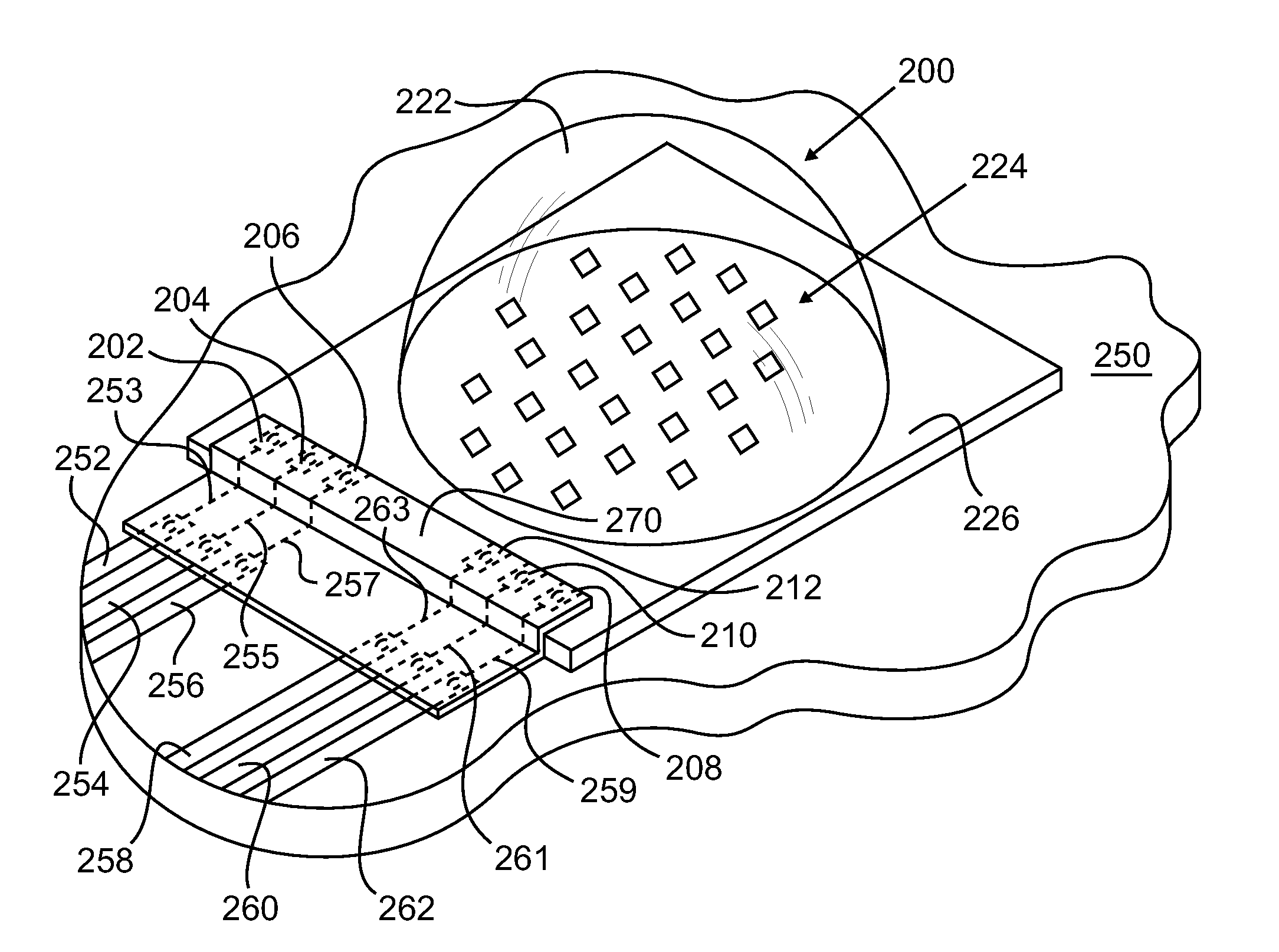
[0021]FIG. 2 illustrates a connector and mounting arrangement in accordance with a first embodiment of the present invention. It shows a packaged LED lamp 200 with multiple top contacts 202, 204, 206, 208, 210 and 212 shown in dashed lines. The lamp 200 further comprises a lens 222 and a mounting substrate 226 which may suitably be a printed circuit board (PCB), such as a flame resistant 4 (FR4) board. The arrangement 200 may also be referred to as an LED, LED lamp or a lamp. The lamp 200 includes three strings of LED chips 224. Each string of LEDs has a cathode and anode contact comprising a pair of the contacts 202-212. It will be recognized that single chip LED lamps, multiple chip lamps with all chips at the same wavelength, multiple chip lamps with chips of different wavelengths and lamps with strings of chips all exist so that myriad contact and drive current requirements are presented. As examples, see U.S. application Ser. Nos. 12 / 154,691 filed May 23, 2008 and 12 / 288,957 fi...


PUM


Abstract

A connector for connecting surface mount devices, such as light emitting diodes (LEDs), to printed circuit boards (PCBs). The connector may be prepackage with an LED assembly or on a PCB to which the LED assembly will be mounted. Connection complexity can be moved from the PCB to the connector, and LED assemblies may be customized differently for different customers. One to many and many to one connections are readily supported with variations on the connector.

Description

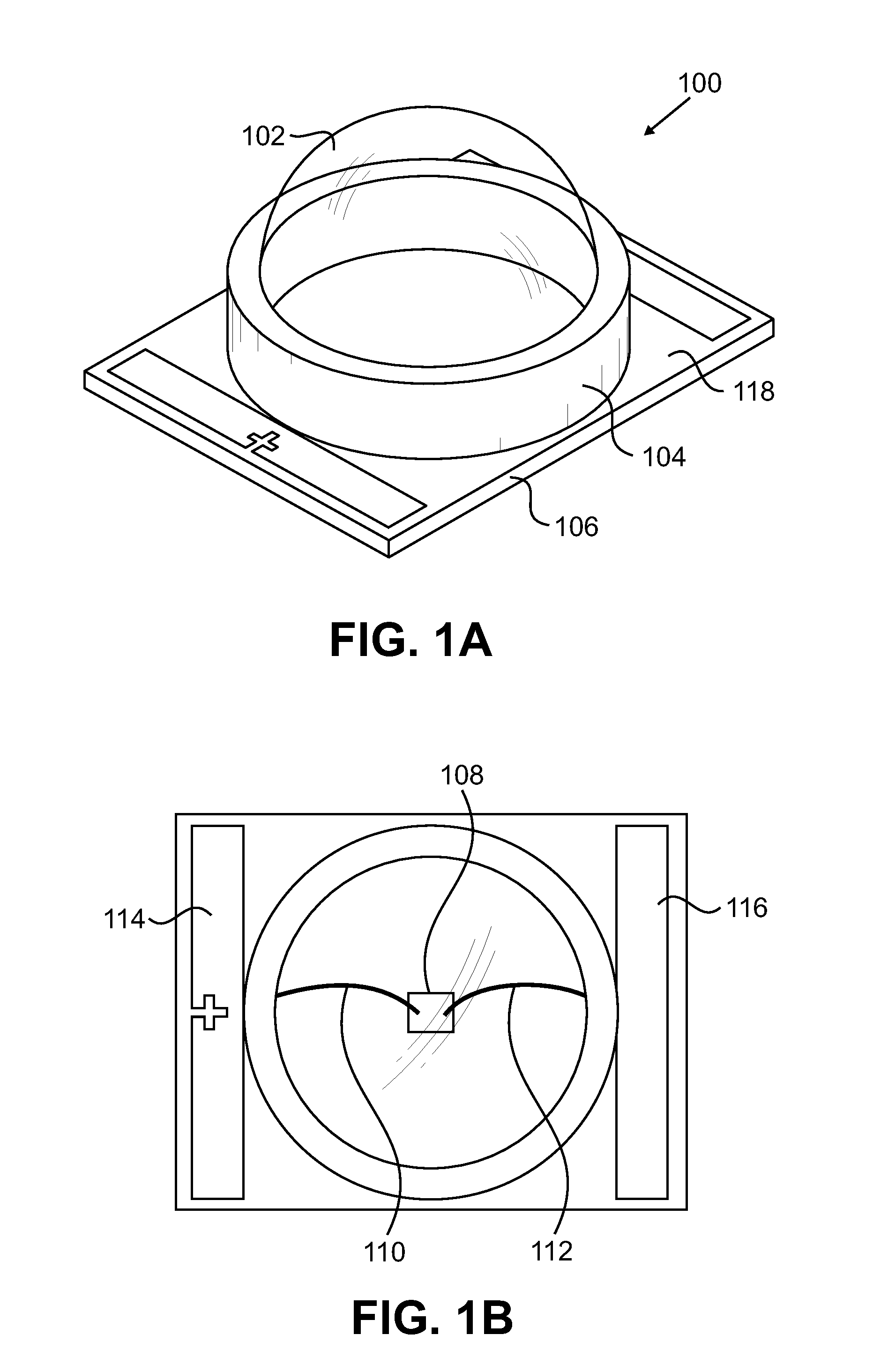
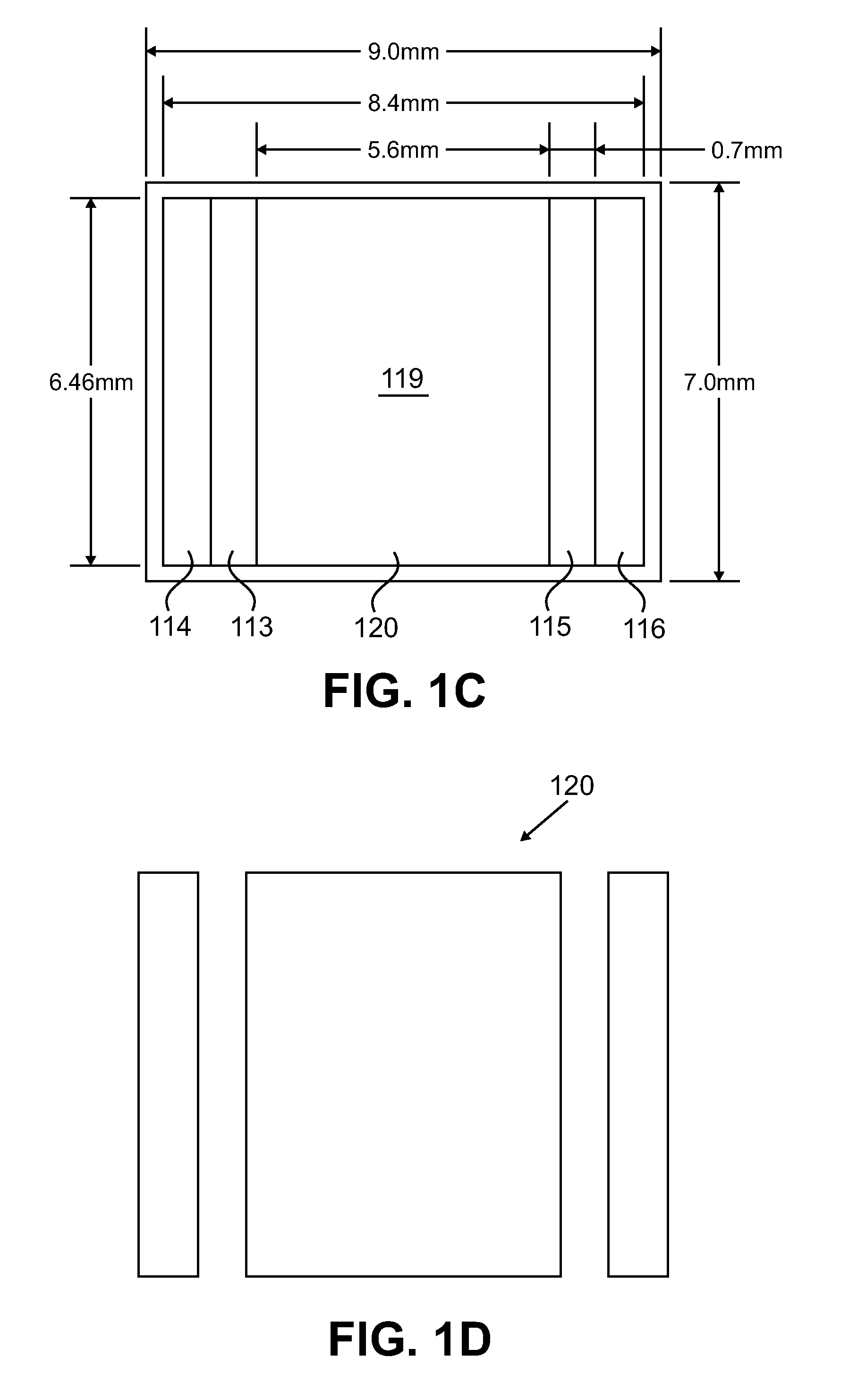
FIELD OF THE INVENTION[0001]The present invention relates generally to improvements in the field of physical mounting and electrical connection arrangements for semiconductor devices, such as light emitting devices, and, in particular, to methods and apparatus for improving the flexibility of light emitting device mounting and electrical connection arrangements.BACKGROUND OF THE INVENTION[0002]FIGS. 1A, 1B, 1C and 1D illustrate a standard LED packaging arrangement, such as that employed by the XLamp® 7090 XR-E series of LED products manufactured by Cree, Incorporated, and how that packaged LED lamp may be suitably mounted on a larger printed circuit board (PCB). As seen in FIG. 1A, the packaged LED lamp 100 comprises a lens 102, a reflector 104 and a mounting substrate 106. The arrangement 100 may also be referred to as an LED, LED lamp or a lamp. As seen in FIG. 1B, an LED chip 108 is electrically connected by bond wires 110 and 112 to electrical contact strips 114 and 116, respect...

Claims


Application Information

Patent Timeline
IPC IPC(8): H05K7/02
CPCF21V19/005F21Y2101/02H01R12/7082H05K1/141H05K1/18H05K3/305H05K3/363H05K2201/10106H05K2201/10681H05K1/147F21Y2115/10
Inventor BIBEE, GREGORY S.
Owner CREELED INC
Learn More