

Gripper bar body for a gripper carriage arrangement
- Summary
- Abstract
- Description
- Claims
- Application Information
AI Technical Summary
Benefits of technology
Problems solved by technology
Method used
Image

Examples
Embodiment Construction
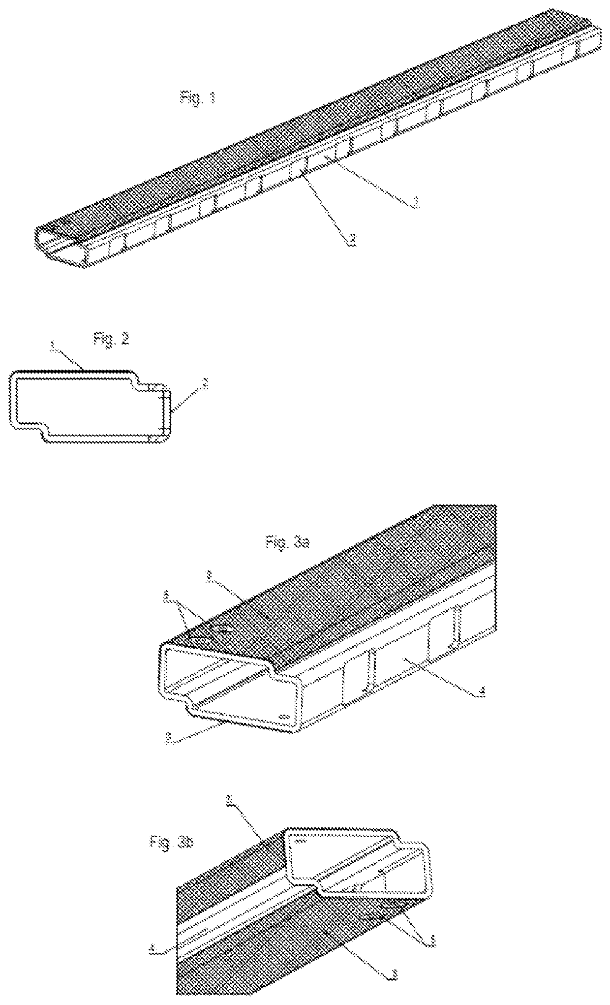
[0013]The invention relates to a gripper bar body for a gripper bar in a gripper carriage arrangement in a machine for treating sheet material. The gripper bar body is being configured to carry gripper brackets for movement between sheet gripping and sheet releasing positions. The gripper bar body is formed as a hollow structure comprising at least two different materials, the two different materials comprising at least a metal material and a composite material. According to the invention the at least two different materials are at least partly arranged in a superposed manner, and the gripper bar body comprises at least two areas of superposed materials.
[0014]A gripper bar body to be used in gripper bar according to the invention shows the advantage, that the area showing the composite material is protected by this material. Further to this, by superposing the materials as described, the rigidity of the gripper bar body may be enhanced.
[0015]Advantageously, where the metal and compo...
PUM
| Property | Measurement | Unit |
|---|---|---|
| Thickness | aaaaa | aaaaa |
| Length | aaaaa | aaaaa |
| Width | aaaaa | aaaaa |
Abstract
Description
Claims
Application Information