
Coil component and manufacturing method therefor

Pending Publication Date: 2020-10-01
MURATA MFG CO LTD
View PDF1 Cites 0 Cited by
  • Summary
  • Abstract
  • Description
  • Claims
  • Application Information

AI Technical Summary

Benefits of technology

The present patent is about a method for making a coil component that is easy to manufacture, has no bonding portions that are a potential concern over reliability, and is reduced to a small size (as small as 1 mm in length). The method involves 3D shaping using a 3D printer to create a three-dimensional structure of the coil component, which includes an annular core and a coil conductor with a spiral conductive wire and terminal electrodes. This technique allows for efficient and precise fabrication of coil components, potentially reducing the risk of bonding failures and allowing for smaller size requirements.

Problems solved by technology

However, it is difficult to mechanize this step, and it is usually necessary to rely on complicated manual operations.
However, both the technique disclosed in Japanese Unexamined Patent Application Publication No. 2001-68364 and the technique disclosed in Japanese Unexamined Patent Application Publication No. 8-203762 described above include problems to be solved.
First, the technique disclosed in Japanese Unexamined Patent Application Publication No. 2001-68364 and the technique disclosed in Japanese Unexamined Patent Application Publication No. 8-203762 both have a problem in that the number of steps for manufacturing the toroidal coil is larger than that of the manual operation for causing a conductive wire to pass through a through-hole of the core every one turn.
In particular, in the technique disclosed in Japanese Unexamined Patent Application Publication No. 2001-68364, there is a serious problem in that, when the core itself which is a main portion of the coil component breaks, a component itself is destroyed.
Furthermore, even if the core itself does not break, there is a problem that inductance acquisition efficiency is lowered due to leakage of magnetic flux at the bonding portion of the core.
On the other hand, in the technique disclosed in Japanese Unexamined Patent Application Publication No. 8-203762, a fatal problem such as disconnection in the spiral conductive wire constituted of the plurality of conductors each having the inverted U-shape and the plurality of conductor films on the wiring board cannot be ignored.
However, at present, in the toroidal coil having the dimension as described above, although it is necessary to perform wire-winding to the annular core, it may be said that it is almost impossible to perform the wire-winding to the annular core.
The wire-winding by manual operation is surely impossible, and even if an automatic wire-winding machine is used, such a small automatic wire-winding machine is not present.
This is also due to the limitation of miniaturization in mechanical aspects, but the main cause is insufficient strength (lack of stiffness) of the conductive wire to be wound.

Method used


Image

  • Coil component and manufacturing method therefor
  • Coil component and manufacturing method therefor
  • Coil component and manufacturing method therefor

Examples


Embodiment Construction

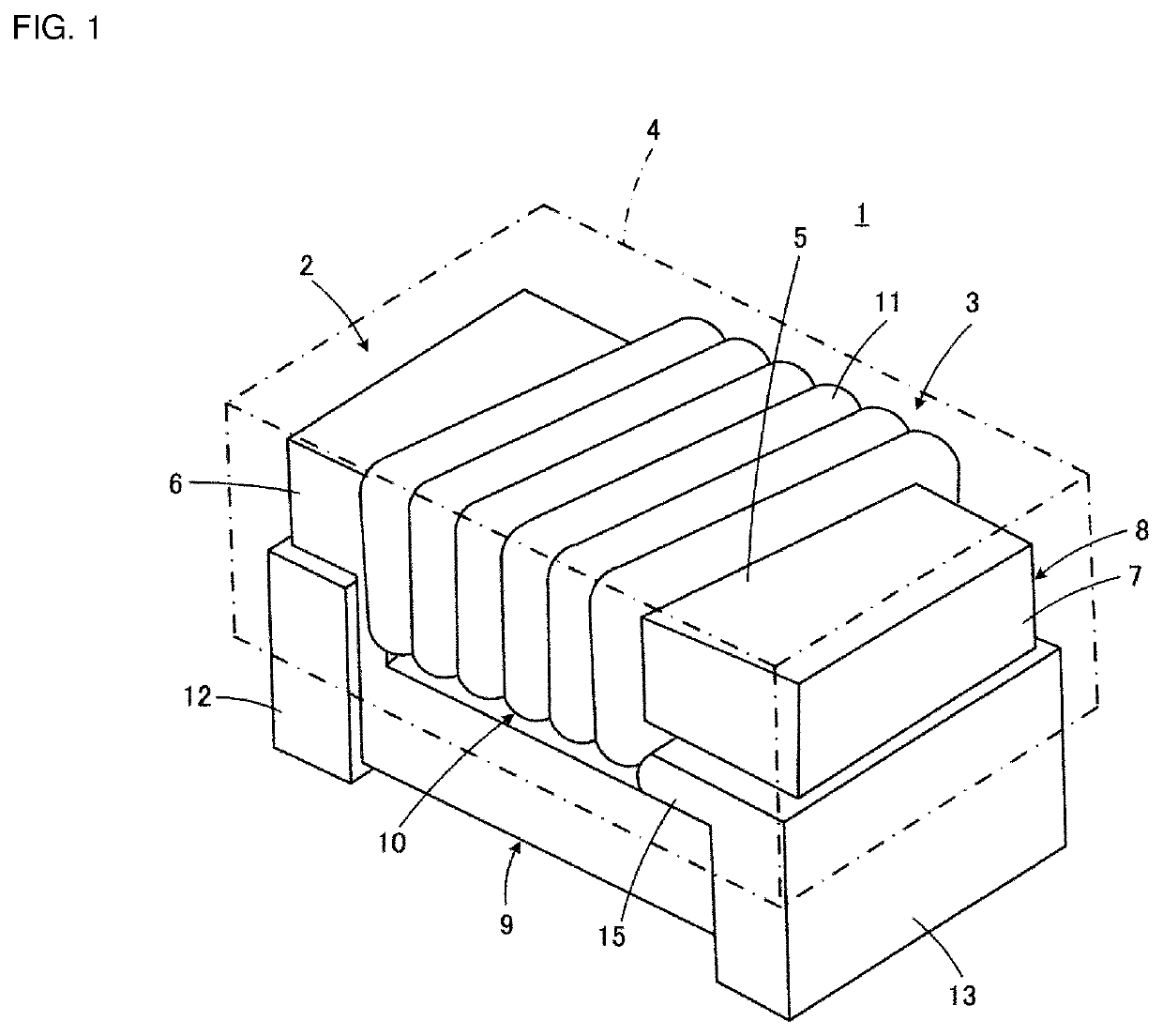
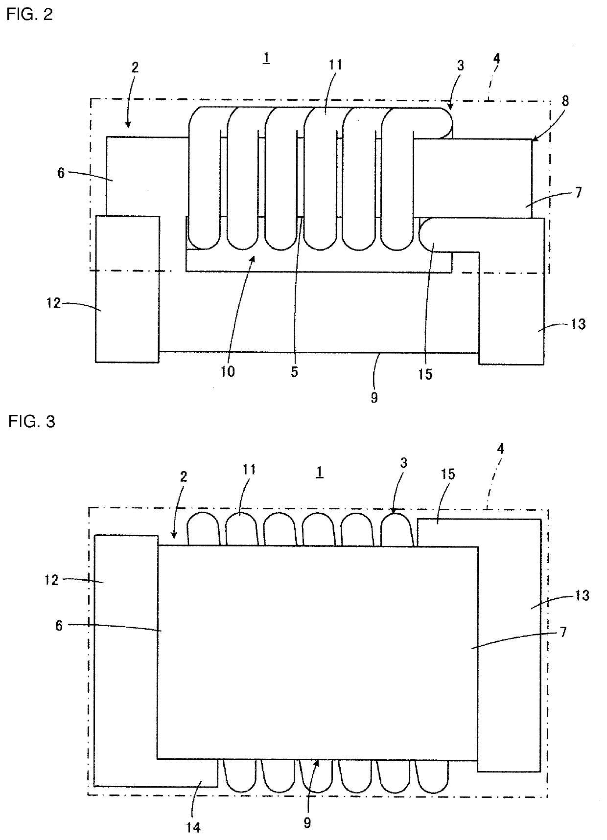
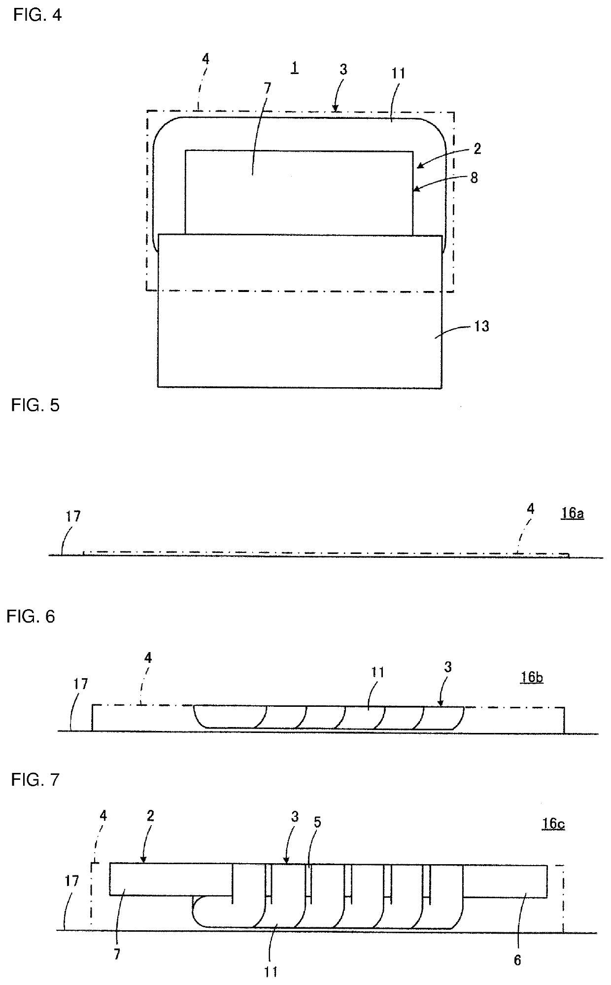
[0046]Referring to FIG. 1 to FIG. 4, a structure of a coil component 1 according to an embodiment of the present disclosure will be described. The illustrated coil component 1 constitutes, for example, a single coil.

[0047]The coil component 1 includes a core 2, a coil conductor 3, and a shape holding member 4. Note that in FIG. 1 to FIG. 4, the shape holding member 4 is indicated by the dot-dash line as a transparent member.

[0048]The core 2 is constituted of a non-conductive material, but is preferably constituted of a magnetic body such as ferrite or a metal magnetic body. However, the core 2 may be constituted of a non-magnetic body such as alumina. The core 2 includes a drum-shaped portion 8 having a winding core portion 5 having a rectangular cross section, and first and second flange portions 6 and 7 respectively provided at a first end and a second end of the winding core portion 5 located on the opposite sides to each other, and includes a plate-shaped portion 9 spanning betw...


PUM


Abstract

A wire wound-type coil component with an integrated structure does not have a bonding portion where there is concern about reliability with respect to a spiral conductive wire, a terminal electrode, and an annular core. A coil component includes a core with an integrated structure, at least part of which is a winding core portion, which has an annular shape having a through-hole, and which is made of a non-conductive material; and a coil conductor with an integrated structure, which has a spiral conductive wire arranged to spirally extend around the winding core portion and first and second terminal electrodes formed at both end portions of the spiral conductive wire, respectively. The coil component is manufactured through three-dimensionally shaping the core, the coil conductor, and a shape holding member for holding a shape of a wall surface of the core defining the through-hole, by using a 3D printer.

Description

CROSS-REFERENCE TO RELATED APPLICATIONS[0001]This application claims benefit of priority to International Patent Application No. PCT / JP2018 / 039317, filed Oct. 23, 2018, and to Japanese Patent Application No. 2018-038775, filed Mar. 5, 2018, the entire contents of each are incorporated herein by reference.BACKGROUNDTechnical Field[0002]The present disclosure relates to a coil component and a manufacturing method therefor, and particularly relates to a coil component including a coil conductor wound around a core and a manufacturing method therefor.Background Art[0003]In a toroidal coil having a structure in which a conductive wire is spirally wound around an annular core made of a magnetic body, for example, the annular core and the spiral conductive wire form an interlinkage structure. In the toroidal coil, a magnetic flux passes through the core while being confined in the annular core, whereby a closed magnetic path is formed. Therefore, the magnetic flux in the core is not affect...

Claims


Application Information

Patent Timeline
IPC IPC(8): H01F27/28H01F27/255H01F27/29H01F41/02H01F41/06
CPCH01F27/2823H01F41/06H01F27/255H01F41/0206H01F27/29H01F17/06H01F41/08H01F27/292Y10T29/53178
Inventor MORINAGA, TETSUYA
Owner MURATA MFG CO LTD
Learn More