Method for making a window and an opening window

Active Publication Date: 2016-02-02
VKR HLDG AS
View PDF40 Cites 0 Cited by
  • Summary
  • Abstract
  • Description
  • Claims
  • Application Information

AI Technical Summary

Benefits of technology

[0004]It is therefore the object of the invention to provide a method of making a

Problems solved by technology

This may for example happen when the plastic becomes soft during a fire or may result from a general deterioration of the material due to wear, exposure to UV radiation

Method used


Image

  • Method for making a window and an opening window
  • Method for making a window and an opening window
  • Method for making a window and an opening window

Examples


Embodiment Construction

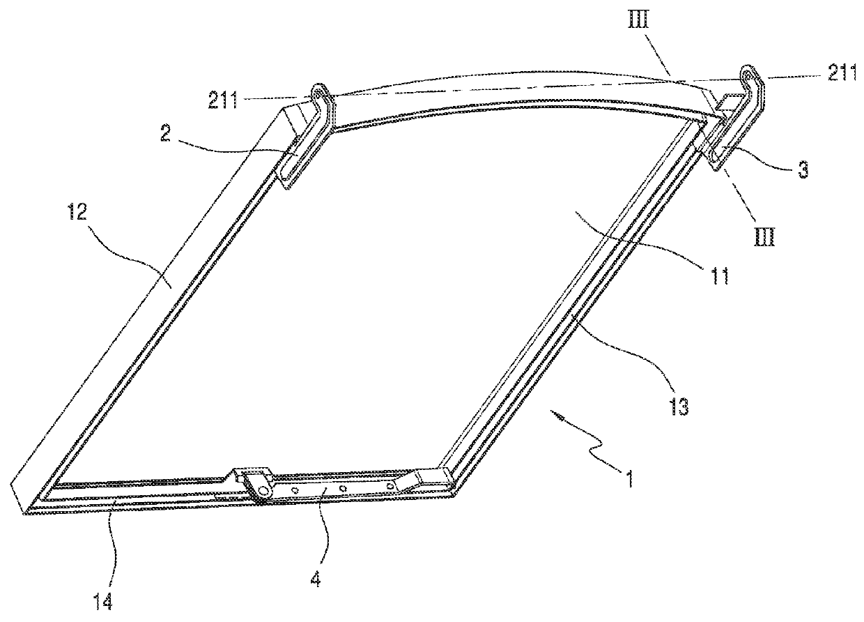
[0023]A sash 1 for a top-hung window according to the invention is shown in FIG. 1. This sash is of a relatively simple construction with first hinge parts 2,3 arranged at the uppermost ends of the sash side members 12,13. A stay arm 4 for opening the window is attached to the bottom member 14 of the sash and intended to cooperate with a pin on the bottom member of a stationary frame (not shown) for keeping the window in an open position.

[0024]In this reference will be made to top, bottom and side members of the sash. This is not to be understood as if the sash must be composed of separate members joint to each other. On the contrary, it preferred that the sash is moulded in one piece.

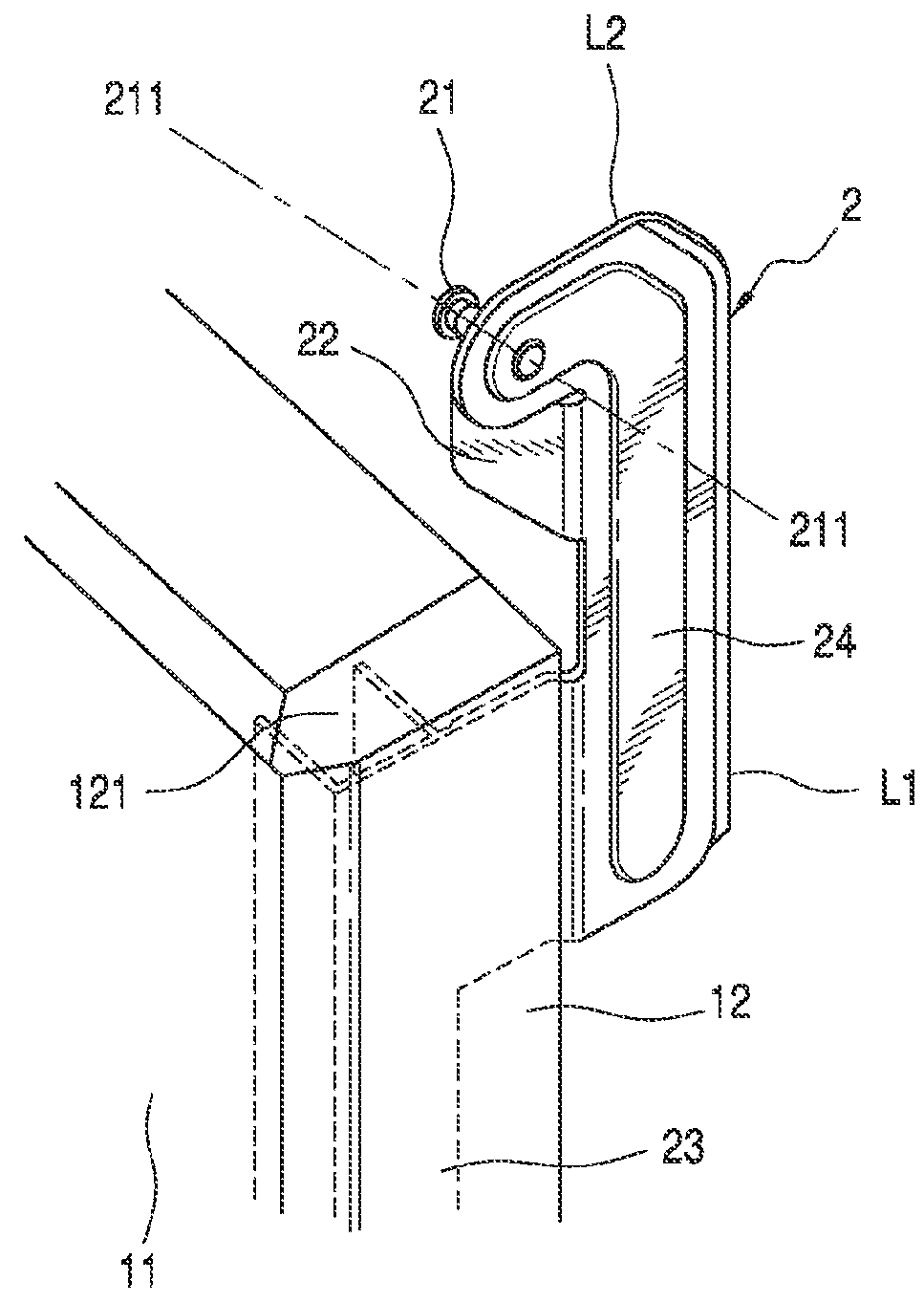
[0025]The first hinge part 2, which will usually be made from plate metal, is shown in more detail and from another angle in FIG. 2. The pin 21 is intended for connecting the first hinge part 2 to a corresponding second hinge part (not shown) on the stationary frame, thus defining a hinge axis 211, and...


PUM

PropertyMeasurementUnit
Volumeaaaaaaaaaa
Volumeaaaaaaaaaa
Volumeaaaaaaaaaa

Abstract

The invention relates a method for making a window, where the sash is connected to the frame by a pair of hinges, each comprising a first hinge part connected to the sash and a second hinge part connected to the frame. The sash is made from a plastic material by molding, and that one or more functional elements are attached to the sash during the molding thereof. The functional elements can include a stay arm having a base member, which is attached to the sash bottom member, and the first hinge parts. Also, the frame may be made by molding.

Description

FIELD OF THE INVENTION[0001]The invention relates to a method for making a window comprising a sash and a frame, each comprising a top member, a bottom member and two side members, where the sash is connected to the frame by a pair of hinges, each comprising a first hinge part connected to a side member of the sash and a second hinge part connected to a side member of the frame. The invention further relates to a window of this kind.[0002]Such windows are known in numerous forms, an example being the cast iron windows used in traditional northern European tile roofs for providing light and ventilation in the attic. These windows are made simply by casting a sash, putting in sheets of glass and fixing them, typically by means of a putty rabbet. The first hinge parts are formed from the cast iron in one with the sash and a base member for attachment of a stay arm may be formed in the same way.[0003]The cast iron windows, however, have poor insulating properties and more modern alterna...

Claims


Application Information

Patent Timeline
IPC IPC(8): E06B3/66
CPCE06B3/6621Y10T29/49826
Inventor KRISTENSEN, LARSNIELSEN, KRISTIAN ORNSVIGSONDERK.AE BUTTED.R, PETER
Owner VKR HLDG AS
Why Eureka
Try Eureka