Fluid dispenser member

a dispenser and fluid technology, applied in the field of fluid dispenser components, can solve the problems of achieve the effect of relatively simple assembly of the dispenser member and relatively complicated assembly of the pump

Inactive Publication Date: 2005-06-23
VALOIS SA
View PDF3 Cites 2 Cited by
  • Summary
  • Abstract
  • Description
  • Claims
  • Application Information

AI Technical Summary

Benefits of technology

[0014] To achieve this object, the present invention proposes a fluid dispenser member designed to be associated with a fluid reservoir and comprising: a chamber in which the fluid is put under pressure, the chamber being provided with an inlet valve and with an outlet; a dispensing orifice; a main piston in leaktight sliding contact inside a main cylinder for the purpose of causing the volume of the chamber to vary; a pusher that can be actuated to generate relative movement between the main piston and the main cylinder; and a differential piston in leaktight sliding contact inside the pusher for the purpose of selectively unmasking the outlet of the chamber; said dispenser member being characterized in that it further comprises stroke-limiting means for limiting the stroke of the differential piston in the pusher, said stroke-limiting means being provided between the pusher and the differential piston. Thus, the differential piston is connected to the pusher in such a manner that its displacement is solely dependent on its interaction with the pusher, and no longer with the body. In this way, the pusher and the differential piston together constitute an independent entity which can be mounted on the body in a single operation. In the above-mentioned prior-art document, the differential piston does not really dependent on the pusher or on the body, so assembling the pump is relatively complicated. With a differential piston contained within the pusher, assembling the dispenser member is much simpler.

Problems solved by technology

In the above-mentioned prior-art document, the differential piston does not really dependent on the pusher or on the body, so assembling the pump is relatively complicated.

Method used


Image

  • Fluid dispenser member
  • Fluid dispenser member
  • Fluid dispenser member

Examples


Embodiment Construction

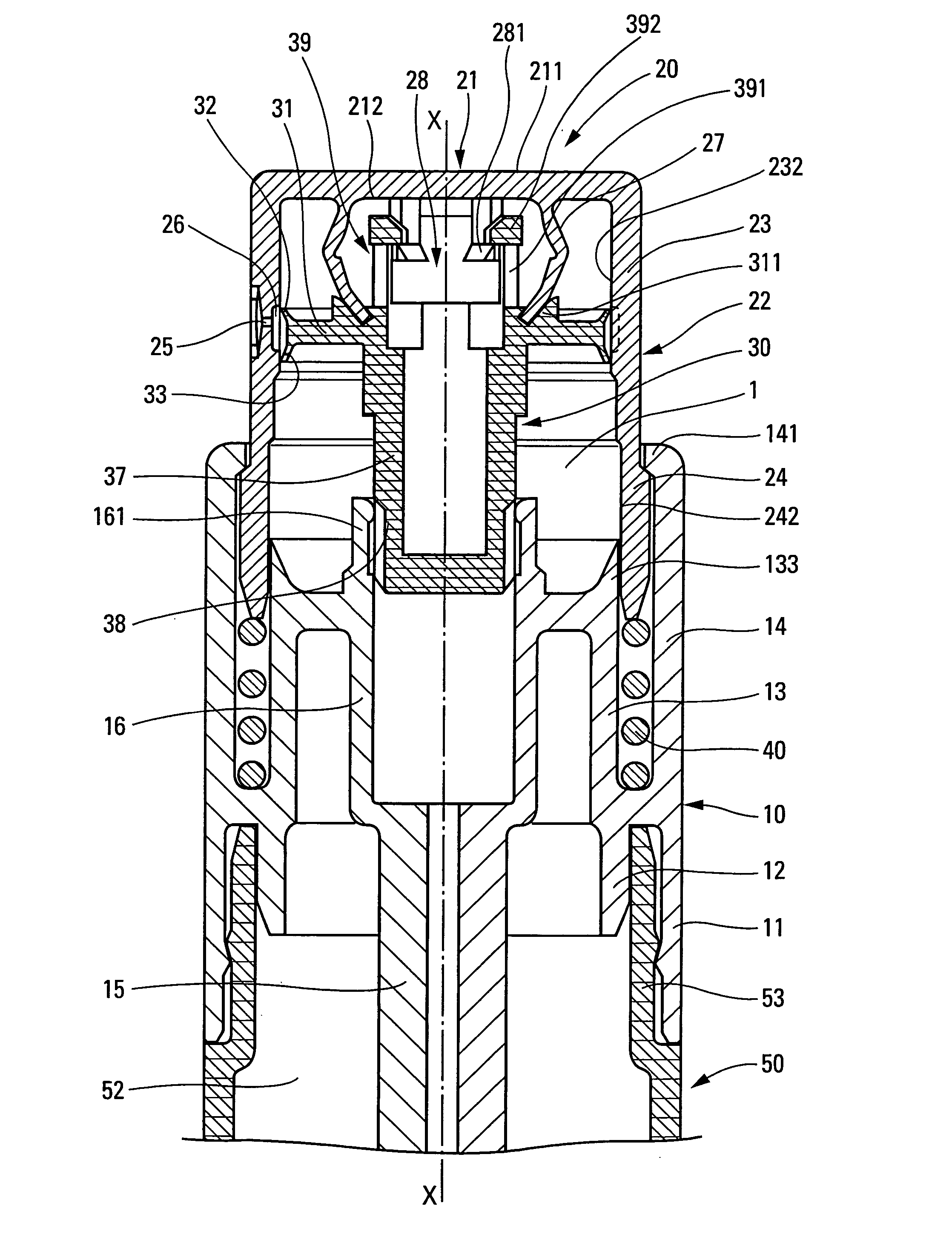
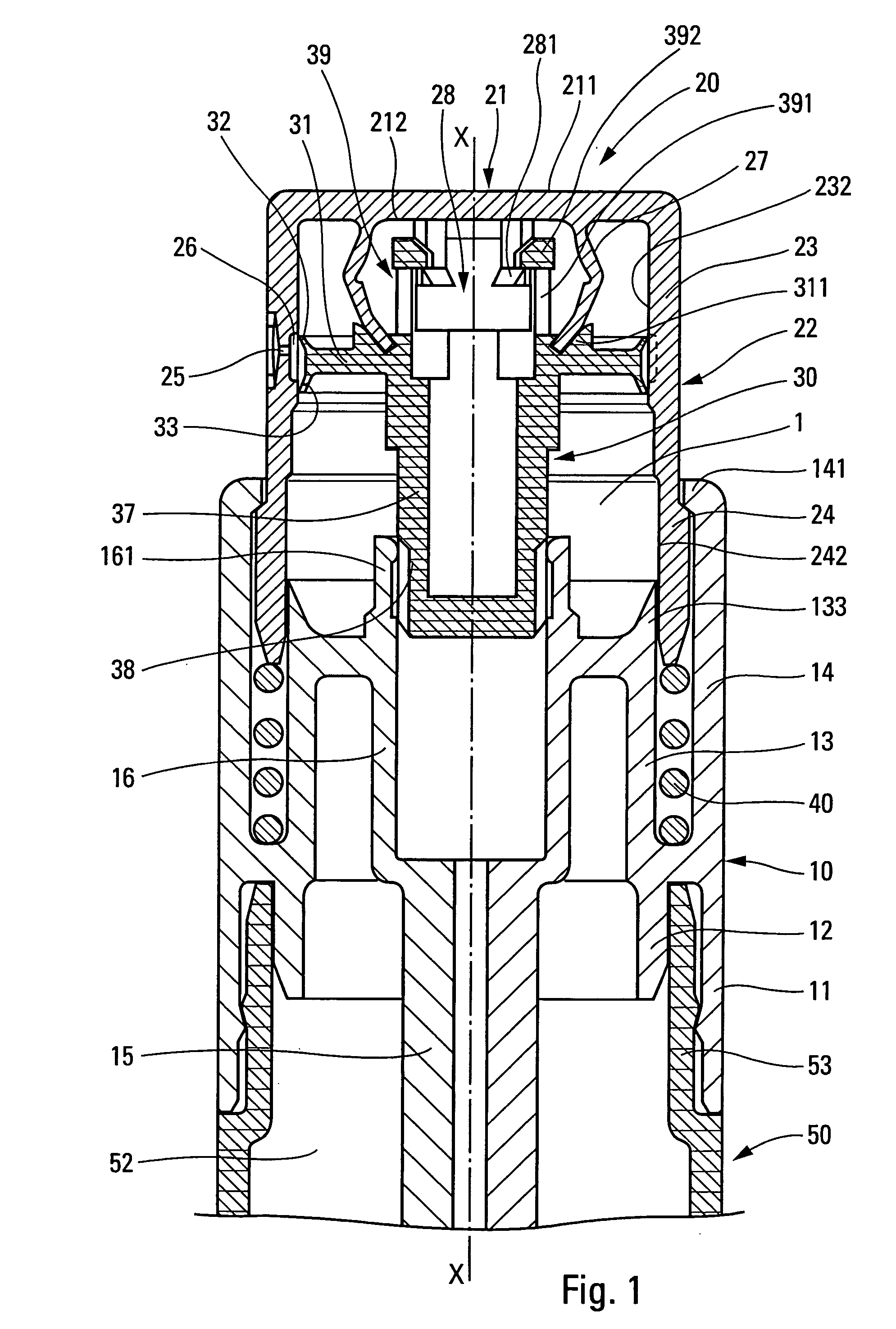
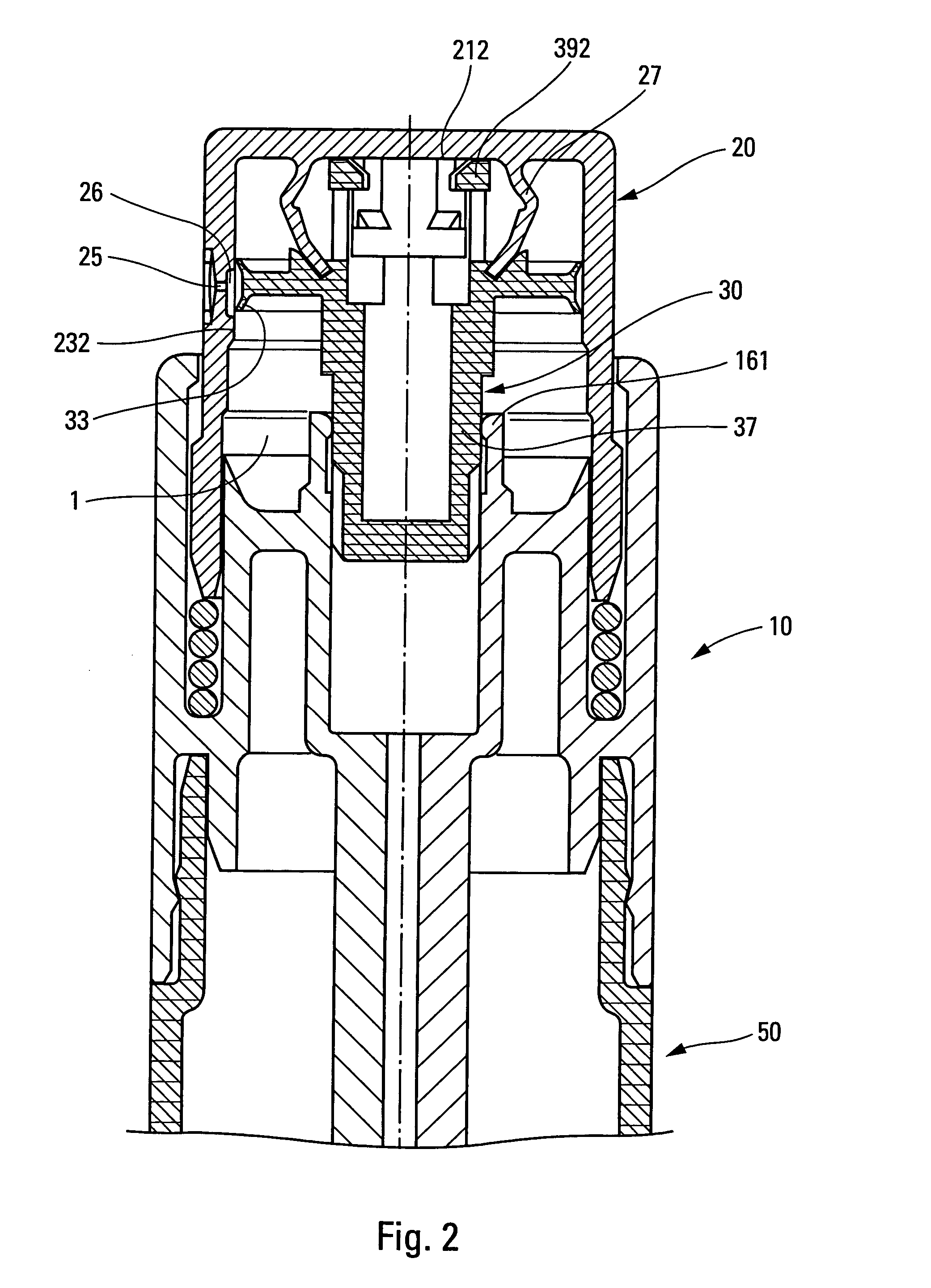
[0025] The embodiment of the dispenser member of the invention shown in FIGS. 1 and 2 is shown in association with a receptacle 50 defining an opening in the form of a neck 53 which advantageously has a fixing profile on its outside surface. The receptacle 50 internally defines a fluid reservoir 5.

[0026] The dispenser member comprises three component elements, namely a body 10, a pusher 20, and a piston member 30. All three parts can be made of a plastics material by injection molding.

[0027] The body 10 has a fixing ring 11 that co-operates with the neck 53 of the receptacle 50. More precisely, the ring 11 comes into engagement around the neck 53. The body 10 can also be provided with a self-sealing lip 12 in sealing contact with the inside wall of the neck 53. A guide band 14 can extend in alignment with the fixing ring 11. At its top end, the ring 14 is provided with an inwardly-extending rim 141 whose function is given below. The body 10 is also provided with a bushing 13 which...


PUM


Abstract

A fluid dispenser member designed to be associated with a fluid reservoir (50) and comprising:
    • a chamber (1) in which the fluid is put under pressure, the chamber being provided with an inlet valve (161, 38) and with an outlet;
    • a dispensing orifice (25);
    • a main piston (133) in leaktight sliding contact inside a main cylinder (242) for the purpose of causing the volume of the chamber to vary;
    • a pusher (20) that can be actuated to generate relative movement between the main piston and the main cylinder; and
    • a differential piston (31, 32, 33) in leaktight sliding contact inside the pusher for the purpose of selectively unmasking the outlet of the chamber;
    • said dispenser member being characterized in that it further comprises stroke-limiting means (28, 39) for limiting the stroke of the differential piston in the pusher, said stroke-limiting means being provided between the pusher and the differential piston.

Description

CROSS REFERENCE TO RELATED APPLICATION [0007] This application claims the benefit under 35 U.S.C. §119(e) of pending U.S. provisional patent application Ser. No. 60 / 561,511, filed Apr. 13, 2004, and priority under 35 U.S.C. §119(a)-(d) of French patent application No. FR-03.15192, filed Dec. 22, 2003.TECHNICAL FIELD [0008] The present invention relates to a fluid dispenser member that is generally designed to be associated with a fluid reservoir so as to constitute therewith a fluid dispenser. It is a dispenser member that is generally actuated manually by means of a user's finger. The fluid is dispensed in the form of a sprayed stream of fine droplets, a continuous trickle, or a dollop of fluid, in particular for viscous fluids, such as cosmetic creams. Such a fluid dispenser member can, in particular, be used in the fields of perfumes, cosmetics, or indeed pharmaceuticals, for dispensing fluids of various viscosities. [0009] The present invention relates more particularly but not ...

Claims


Application Information

Patent Timeline
Patent Type & Authority Applications(United States)
IPC IPC(8): B05B11/00
CPCB05B11/3004B05B11/304B05B11/3077B05B11/3074B05B11/307B05B11/1004B05B11/104B05B11/107B05B11/1077B05B11/1074
Inventor GARCIA, FIRMIN
Owner VALOIS SA
Why Eureka
Try Eureka