

Mercury-free arc tube for a discharge lamp
- Summary
- Abstract
- Description
- Claims
- Application Information
AI Technical Summary
Benefits of technology
Problems solved by technology
Method used
Image

Examples
first embodiment
[0098] Other portions are similar to those in the above first embodiment, and their redundant explanation will be omitted herefrom by affixing the same reference symbols to them.
second embodiment
[0099] Also, in the above second embodiment, an example in which the cross section of the base-end side area 16A of the electrode rod is formed as the deformed sectional shape is given. As other embodiment in which the cross section of the base-end side area 16A of the electrode rod is formed as the deformed sectional shape, the case where the cross section is shaped into a part of a circle shown in FIG. 7 and FIG. 8 may be considered.
[0100] In a base-end side area 16B of the electrode rod in a third embodiment of the present invention shown in FIG. 7, the cross section is shaped into a shape obtained by cutting away a cylinder up to a position just including a longitudinal axis, and a ratio A1 / A2=2 is set. Also, in a base-end side area 16C of the electrode rod in a fourth embodiment shown in FIG. 8, the cross section is shaped into a shape obtained by cutting away a cylinder up to a position that exceeds a longitudinal axis, and a ratio A1 / A2=4.5 is set. Reference symbols 16×3, 16×...
fifth embodiment
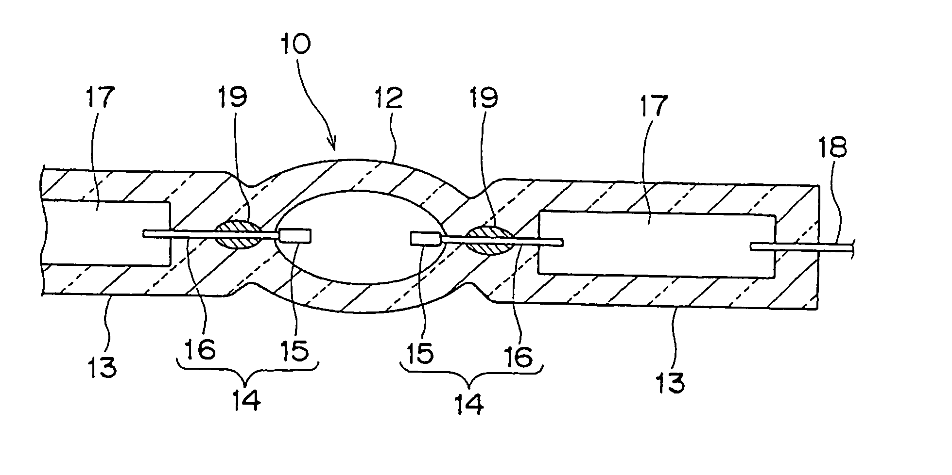
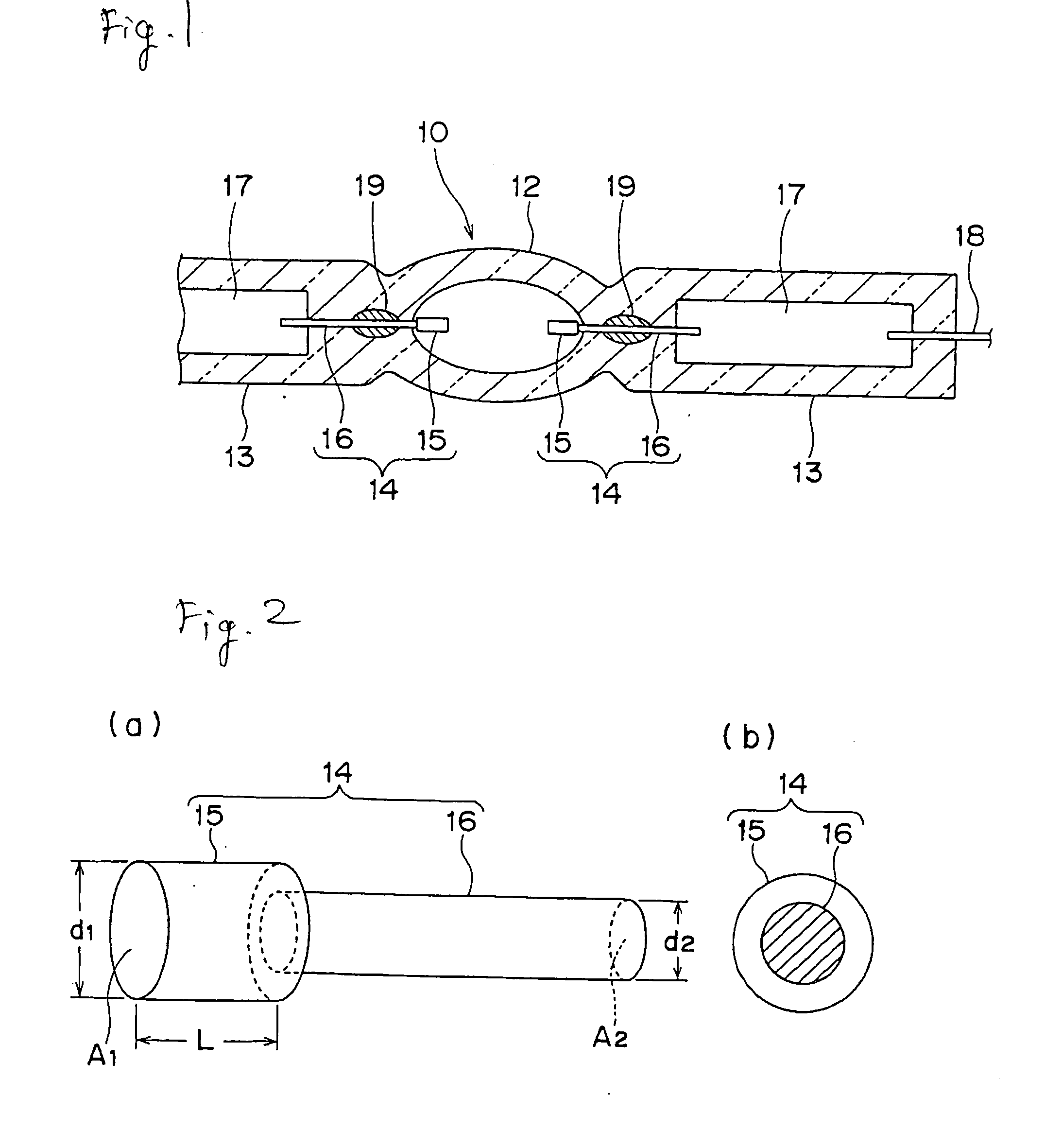
[0101]FIG. 9 is an enlarged side view showing an electrode rod as a pertinent portion of an arc tube for a discharge lamp as the present invention.
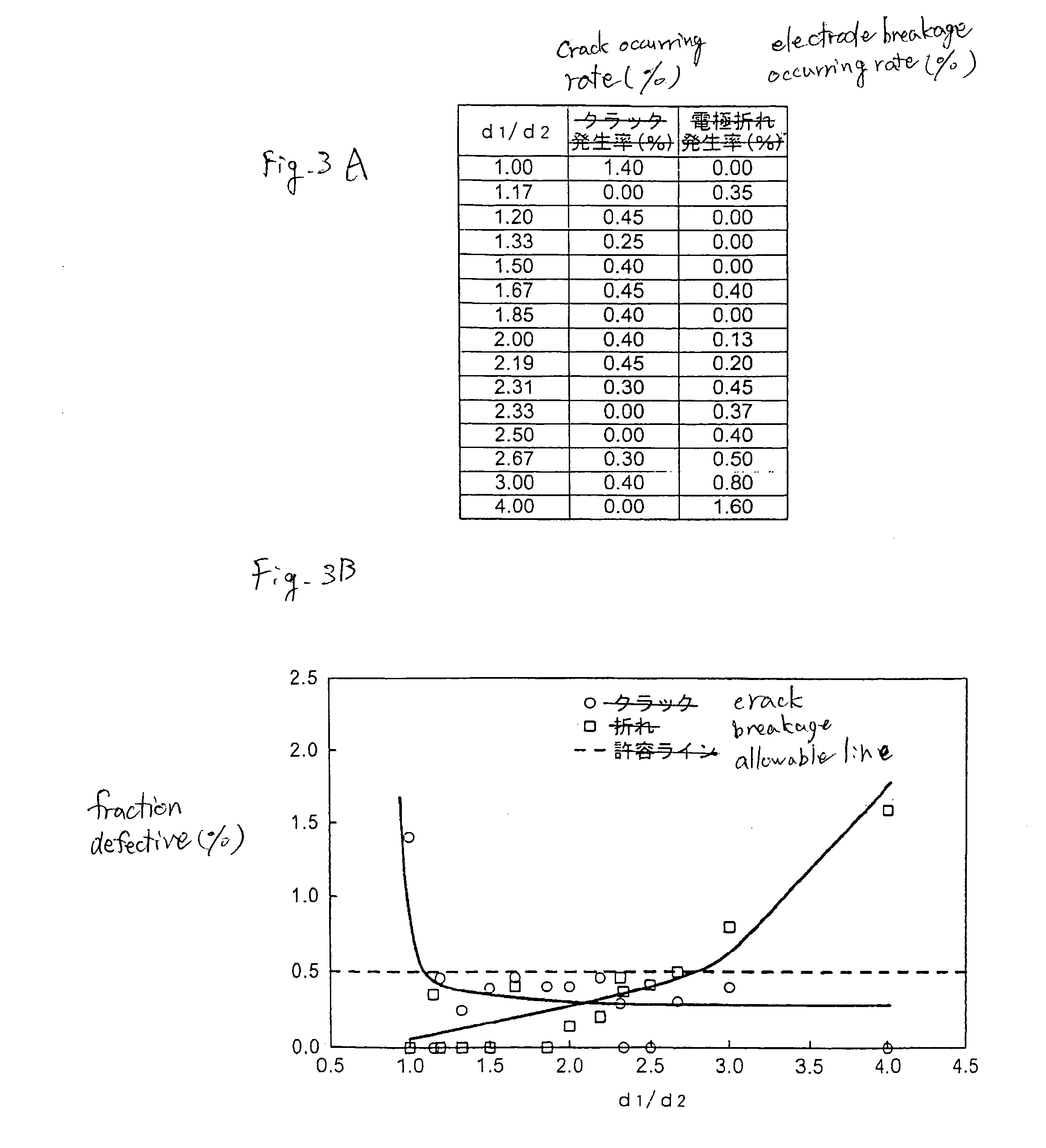
[0102] An electrode rod 14D in the fifth embodiment has such a structure that a tungsten coil C is fitted integrally onto the top-end side area of the main body of the tungsten electrode rod having an outer diameter d2. A ratio d1 / d2 of the outer diameter d1 of the top-end side area 15A, which corresponds coil C, of the electrode rod to the outer diameter d2 the base-end side area 16 of the electrode rod is set in a range of 1.2 to 2.7.
PUM
 Abstract
Description
Claims
Application Information