Loop antenna device

a loop antenna and antenna technology, applied in the field of loop antenna devices, can solve the problems of undesired magnetic field reaching, undesired balance between loop antenna cells, and practically impossible to maintain or obtain balan

Inactive Publication Date: 2005-06-23
SEIKO EPSON CORP +1
View PDF9 Cites 19 Cited by
  • Summary
  • Abstract
  • Description
  • Claims
  • Application Information

AI Technical Summary

Benefits of technology

[0016] The present invention is further characterized in that the plurality of small loop antenna cells are respectively provided with electric field shielding conductors that reduce electric field components emitted from the small loop antenna cells. Each of the electric filed shielding conductors has a gap for preventing formation of a short ring.

Problems solved by technology

That is, even if the loop antenna device is designed in such a way that the intensity of the alternating magnetic field is abruptly lowered when the alternating field is remote from the loop size as described above, the influence of an environment around the loop antenna device causes an imbalance between the loop antenna cells, resulting in a strong magnetic field undesirably reaching a position remote from the loop size.
Thus, when the loop antenna device is assembled into the reader / writer device, the intended balance between the loop antenna cells may be undesirably deteriorated.
Further, even if the loop antenna device is assembled into the reader / writer device with good balance, it would be practically impossible to maintain or obtain the balance, taking into account the environment around the loop antenna device, when the reader / writer device is installed.
Further, when a tag is placed on a specific one of the antenna cells, induced current flowing through a coil of the tag also causes a problem in which the balance between the loop antenna cells may be deteriorated similarly to the above-described case.
In short, the solution in which the plurality of loop antenna cells are combined together to adjust the sum total of the magnetic moments to be “0” still suffers from a problem in which the intended balance between the loop antenna cells is readily deteriorated in practical use.

Method used


Image

  • Loop antenna device
  • Loop antenna device
  • Loop antenna device

Examples


Embodiment Construction

[0026] Now, an embodiment of a loop antenna device according to the present invention will be described by referring to the accompanying drawings.

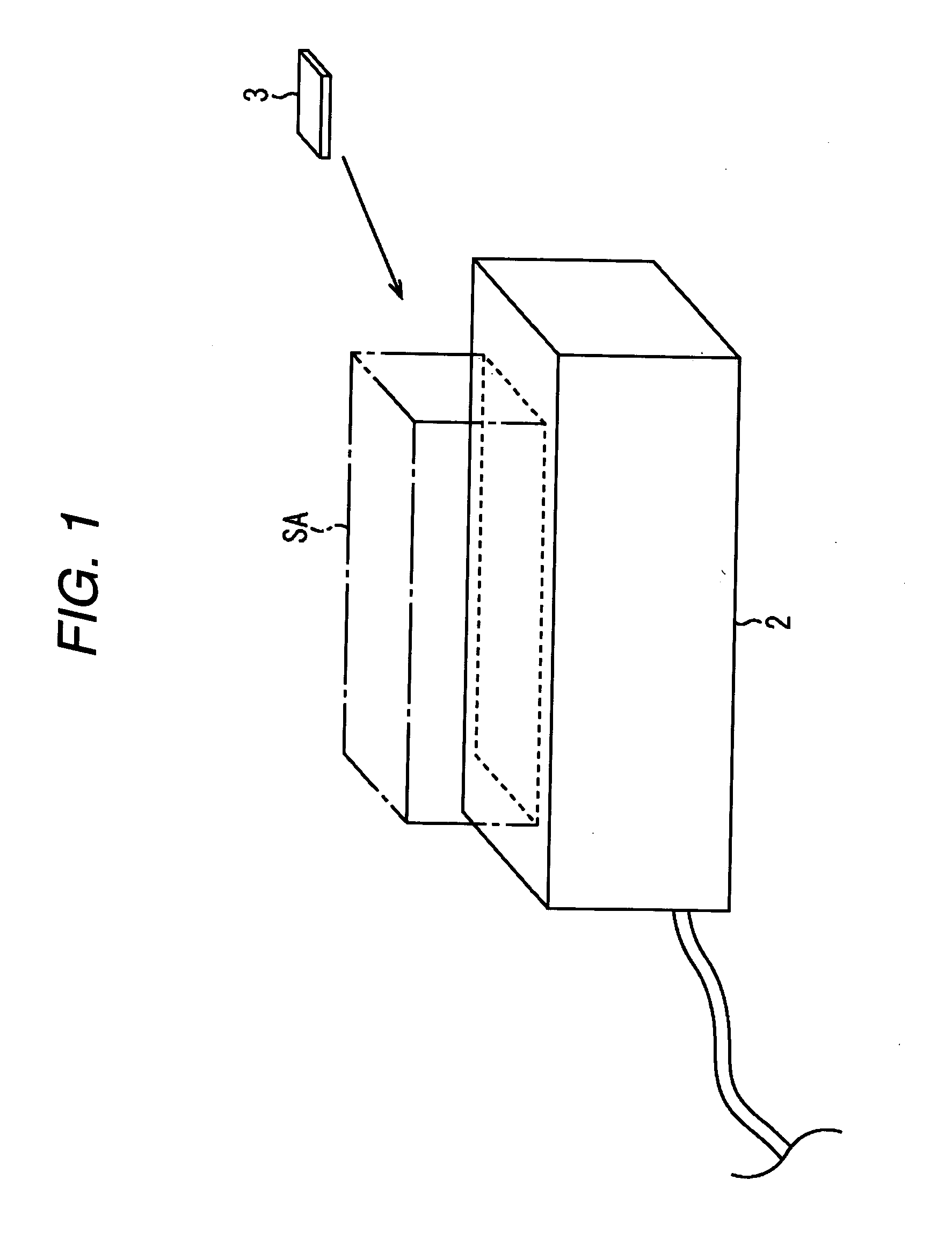
[0027]FIG. 1 shows one example of a situation in which the loop antenna device of this embodiment is employed and a data carrier 3 is allowed to come near to a service area SA of a reader / writer device 2.

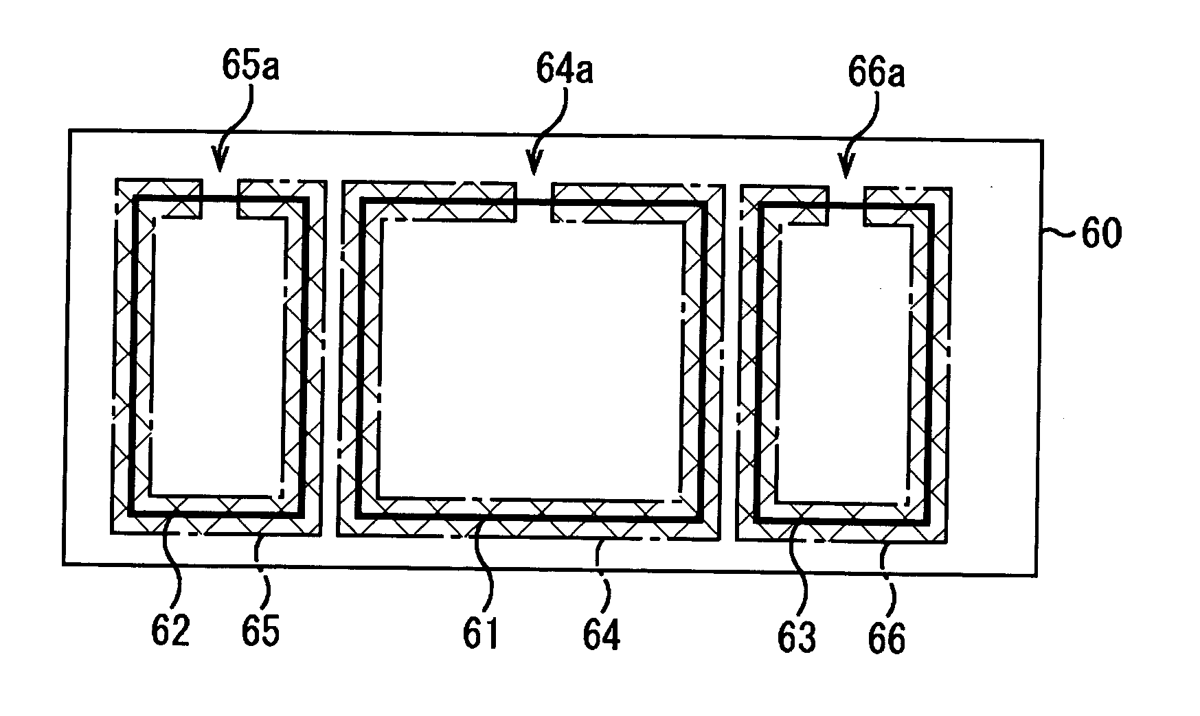
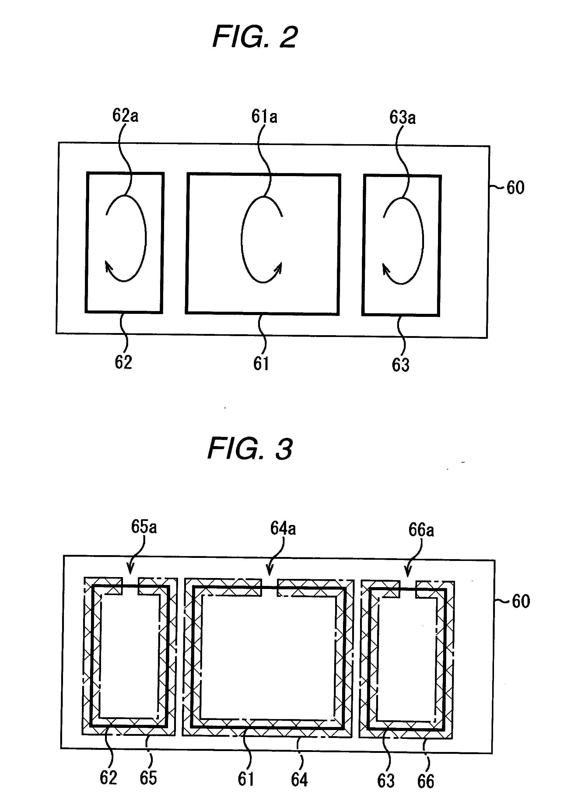
[0028] As shown in FIG. 2, a loop antenna device according to this embodiment has three small loop coils for data transmission, i.e. a first small loop coil 61, a second small loop coil 62 and a third small loop coil 63 that are formed on a base 60. The loop antenna device according to the present invention may have more number of small loop coils.

[0029] The first small loop coil 61 has an area two times as large as that of the second small loop coil 62 or the third small loop coil 63. Further, as shown in FIG. 2, the direction of an alternating magnetic field 61a generated in the first small loop coil 61 is opposite to those of alterna...


PUM


Abstract

A plurality of small loop antenna cells 61, 62 and 63 are magnetically coupled to an antenna coil 8 of a non-contact type data carrier 3. In the plurality of small loop antenna cells, the directions of the magnetic moments of the signals transmitted to the non-contact type data carrier 3 are opposite to each other, the sum of the magnetic moments generated from all the small loop antenna cells 61 to 63 is zero and a conductor forming a short ring pattern 67 is provided collectively for the plurality of small loop antenna cells. Thus, imbalance caused between the small loop antenna cells 61 to 63 can be compensated for by the short ring pattern 67.

Description

BACKGROUND OF THE INVENTION [0001] The present invention relates to a loop antenna device and more particularly to a loop antenna device preferably used for a reader / writer device of an electromagnetic induction type non-contact data carrier system in which data transmission and reception are executed in a non-contact state between a plurality of data carriers and the loop antenna device. [0002] In general, a data carrier system includes a reader / writer device and a data carrier. An antenna device of the reader / writer device supplies a modulated alternating magnetic field to a service area to transmit data or a command to the data carrier. [0003] The data carrier receives the modulated alternating magnetic field supplied to the service area using an incorporated coil to generate electromotive voltage that is rectified and used as an operating power source of the data carrier. The data carrier also executes prescribed operations, such as demodulation of the modulated alternating magn...

Claims


Application Information

Patent Timeline
Patent Type & Authority Applications(United States)
IPC IPC(8): G06K7/08H01Q7/04
CPCG06K7/10336H01Q7/04G08B13/2474
Inventor FUKANO, TAKAKAZUKOSUGI, YASUHIKOASAUCHI, NOBORUISHII, EIICHI
Owner SEIKO EPSON CORP
Why Eureka
Try Eureka