Gate driving apparatus and method for liquid crystal display

Active Publication Date: 2005-06-23
LG DISPLAY CO LTD
View PDF6 Cites 39 Cited by
  • Summary
  • Abstract
  • Description
  • Claims
  • Application Information

AI Technical Summary

Benefits of technology

[0023] An object of the present invention is to provide an apparatus for driving a gate of a liquid crystal display having a reduced number of data lines and data driving integrated circuits.

Problems solved by technology

However, the related art LCD has a problem in that it has a high manufacturing cost caused by the multitude of data lines D1 to Dm provided at the liquid crystal display panel 13 and the multitude of driving integrated ci

Method used


Image

  • Gate driving apparatus and method for liquid crystal display
  • Gate driving apparatus and method for liquid crystal display
  • Gate driving apparatus and method for liquid crystal display

Examples


Embodiment Construction

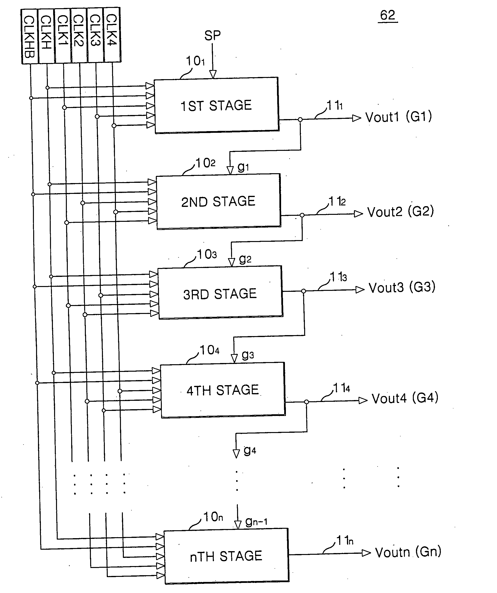
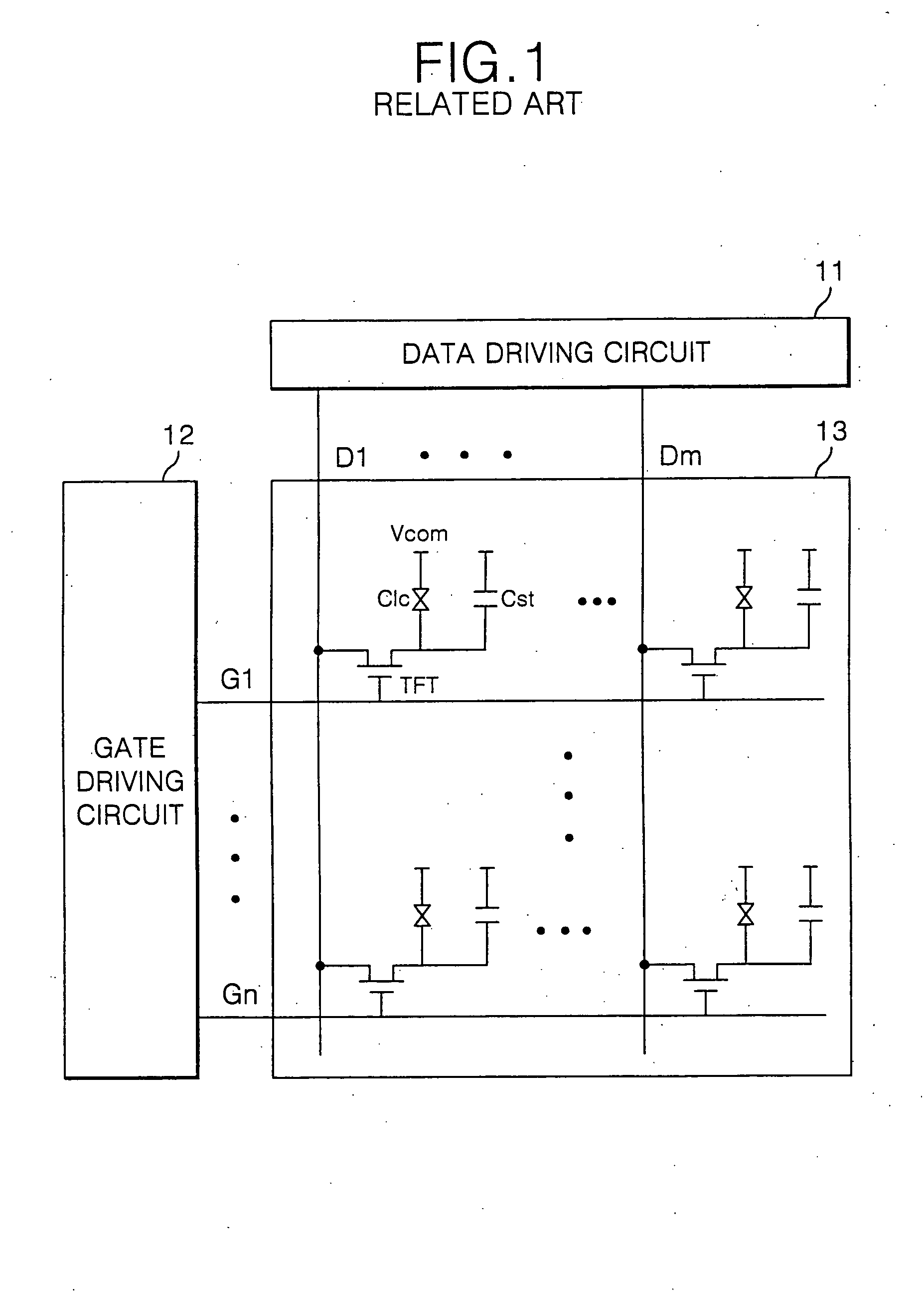
[0044]FIG. 6 is an exemplary schematic block diagram of a configuration of a liquid crystal display device according to an embodiment of the present invention. Referring to FIG. 6, the LCD according to the embodiment of the present invention can include a liquid crystal display panel 63 having (m×n) liquid crystal cells Clc in a matrix arrangement and m / 2 data lines D1 to Dm / 2 and n gate lines G1 to Gn intersecting each other. The LCD also includes a data driving circuit 61 for applying a data to the data lines D1 to Dm / 2 of the liquid crystal display panel 63. A gate driving circuit 62 is provided for applying a scanning pulse to the gate lines G1 to Gn. A timing controller 64 is provided for controlling the data driving circuit 61 and the gate driving circuit 62. A power generator 65 is provided for generating a driving voltage required for a driving of the liquid crystal display panel 63.

[0045]FIG. 7 is an exemplary circuit diagram of a portion of pixel cells in a liquid crystal...


PUM


Abstract

A gate driving apparatus for a liquid crystal display includes a shift register which is provided with first and second half-period clock signals having phases inverted with respect to each other and each having a pulse width of a half-period, first to fourth one-period clock signals having phases shifted sequentially and each having a pulse width of one period, a start pulse, a high-level supply voltage and a low-level supply voltage. The shift register generates a half-period output in response to the start pulse and the first and second half-period clock signals. The shift register also generates a one-period output at a half-period delay from an end time of the half-period output in response to any one of the first to fourth one-period clock signals.

Description

[0001] The present invention claims the benefit of Korean Patent Application No. 92694 / 2003 filed in Korea on Dec. 17, 2003, which is hereby incorporated by reference. BACKGROUND OF THE INVENTION [0002] 1. Field of the Invention [0003] The present invention relates to a liquid crystal display, and more particularly to a gate driving apparatus and a gate driving method in a liquid crystal display. [0004] 2. Discussion of the Related Art [0005] In general, a liquid crystal display (LCD) controls a light transmittance of a liquid crystal using an electric field to thereby display a picture. [0006]FIG. 1 is a schematic view of a configuration of a an active matrix liquid crystal display device in accordance with the related art. Referring to FIG. 1, the active matrix LCD includes a liquid crystal display panel 13. The LCD panel 13 comprises (m×n) liquid crystal cells Clc in a matrix arrangement, m data lines D1 to Dm and n gate lines G1 to Gn intersecting each other. TFT's are provided ...

Claims


Application Information

Patent Timeline
IPC IPC(8): G02F1/133G09G3/20G09G3/36G11C19/00G11C19/28
CPCG09G3/3688G09G2310/02G11C19/28G11C19/00G09G2310/0297G02F1/133
Inventor JANG, YONG HOKIM, BINNYOON, SOO YOUNG
Owner LG DISPLAY CO LTD
Why Eureka
Try Eureka