Mobile communication terminal equipped with camera and method of controlling the same

a mobile communication terminal and camera technology, applied in the field of mobile communication terminals, can solve the problems of high cost of optical sensor ic for detecting light intensity, no gpio terminal available for other application operations in the mobile communication terminal, and no gpio terminal available for other application operations, etc., and achieve the effect of high-quality pictur

Inactive Publication Date: 2005-06-23
CURITEL COMM
View PDF8 Cites 9 Cited by
  • Summary
  • Abstract
  • Description
  • Claims
  • Application Information

AI Technical Summary

Benefits of technology

[0010] The present invention provides a mobile communication terminal equipped with a camera and a method capable of taking a high-quality picture by activating a flash according to ambient luminance when the camera takes a picture.
[0011] The present invention also provides a mobile communication terminal with a camera and a method capable of easily varying in a software manner a luminance threshold value used in activating the flash.

Problems solved by technology

Firstly, there is a problem in that the optical sensor IC for detecting the light intensity is expensive.
As a result, the total manufacturing cost for the mobile communication terminal increases significantly.
Secondly, since some of the GPIO terminals, which are provided in the MSM to be used for application operations in the mobile communication terminal, are used to trigger the flash, it may occur that there are no GPIO terminals available for other application operations in the mobile communication terminal.
Furthermore, there is a problem in that since a threshold value, which is used in determining whether the light intensity detected by the optical IC is high or low, is set in a hardware manner, the threshold value cannot be readjusted once the mobile communication terminal has been assembled.

Method used


Image

  • Mobile communication terminal equipped with camera and method of controlling the same
  • Mobile communication terminal equipped with camera and method of controlling the same
  • Mobile communication terminal equipped with camera and method of controlling the same

Examples


Embodiment Construction

[0033] Exemplary embodiments in accordance with the present invention will now be described in detail with reference to the accompanying drawings.

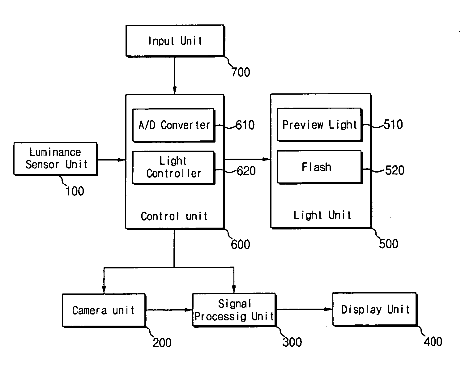
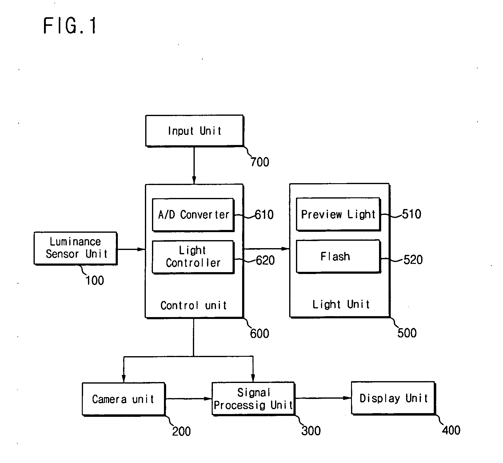
[0034]FIG. 1 is a block diagram showing the configuration of a mobile communication terminal in accordance with the present invention. The mobile communication terminal comprises an input unit 700, a display unit 400, a luminance sensor unit 100, a camera unit 200, a signal processing unit 300, a light unit 500 and a control unit 600.

[0035] The input unit 700 receives a user command and transfers the user command to the control unit 600 so that the camera unit 200 can take a picture and output the picture in response to the user command. The display unit 400 displays a picked-up image inputted through a lens system under the control of the control unit 600. The input unit 700 and the display unit 400 can employ well-known configurations.

[0036] The control unit 600 compares a value indicating light intensity based on an electrical signal...


PUM


Abstract

Disclosed are a mobile communication terminal and a method capable of taking a high-quality picture by providing a flash or light function according to ambient luminance when a camera mounted in the mobile communication terminal takes a picture. The mobile communication terminal equipped with a camera includes: a luminance sensor unit for outputting an analog electrical signal proportional to ambient luminance; a control unit for generating a preview light enable signal according to the analog electrical signal; and a preview light for emitting light in a preview mode in response to the preview light enable signal. In addition, a method of controlling a mobile communication terminal equipped with a camera unit and a light unit includes the steps of: enabling a luminance sensor unit to detect ambient luminance according to a camera mode selection command; comparing a light intensity value obtained from a signal outputted from the luminance sensor unit with a pre-programmed threshold value; and controlling the operation of the light unit according to the comparison result.

Description

BACKGROUND OF THE INVENTION [0001] This application claims the priority of Korean Patent Application No. 2003-94310, filed on Dec. 20, 2003, in the Korean Intellectual Property Office, the disclosure of which is incorporated herein in its entirety by reference. [0002] 1. Field of the Invention [0003] The present invention relates to a mobile communication terminal and, more particularly, to a mobile communication terminal equipped with a camera in which a flash is triggered according to ambient luminance and a method of controlling the mobile communication terminal equipped with a camera. [0004] 2. Description of Related Art [0005] In general, when a camera module incorporated in a mobile communication terminal is operated, a preview mode is triggered to display a picked-up image, which is projected through a lens system, on a liquid crystal display (LCD). The displayed image is captured when a picture-taking button is pressed. The captured image is compressed and stored in an inter...

Claims


Application Information

Patent Timeline
Patent Type & Authority Applications(United States)
IPC IPC(8): H04N5/235H04B1/40H04N9/68
CPCH04N5/2354H04N23/74H04B1/40
Inventor MOON, JUN-HORYU, WON-IKJEONG, KI-HYUNGSON, SUNG-IL
Owner CURITEL COMM
Why Eureka
Try Eureka