Method of converting resolution of video signals and apparatus using the same

a technology of video signals and resolution, applied in the field of video signal resolution conversion and the same, can solve problems such as blurring, deterioration, zigzag artifacts and moiré patterns,

Active Publication Date: 2005-06-23
SAMSUNG ELECTRONICS CO LTD
View PDF6 Cites 119 Cited by
  • Summary
  • Abstract
  • Description
  • Claims
  • Application Information

AI Technical Summary

Problems solved by technology

In the case of the resolution extension, since new signal components are interpolated between samples of an original input signal, a blurring takes place due to losses of high frequency components when the signals are being filtered.
Also, in the case of the resolution reduction, since high frequency components in an input video are aliased on a low frequency signal, deterioration, such as a zigzag artifact and a moiré pattern, occurs.
However, since high frequency components of the input video are not sufficiently extended during the resolution extension, both the definition and the display quality deteriorate.
However, such a scaling method uses a conventional linear filter, and thus, has a problem that both pre-processing and post-processing require an increase in arithmetic operations and additional hardware, thus causing costs to increase because the peaking and the luminance transition enhancement should be accomplished for the video signals in both pre-processing and post-processing stages during filtering to improve the display quality and the definition of a video.
However, fine textured regions of a video cannot be processed with high definition.
In addition, their performances are unsatisfactory compared to the linear filtering technique, with the exception of most regions of the edge components.

Method used


Image

  • Method of converting resolution of video signals and apparatus using the same
  • Method of converting resolution of video signals and apparatus using the same
  • Method of converting resolution of video signals and apparatus using the same

Examples


Embodiment Construction

[0035] Reference will now be made in detail to the embodiments of the present invention, examples of which are illustrated in the accompanying drawings, wherein like reference numerals refer to the like elements throughout. The embodiments are described below to explain the present invention by referring to the figures.

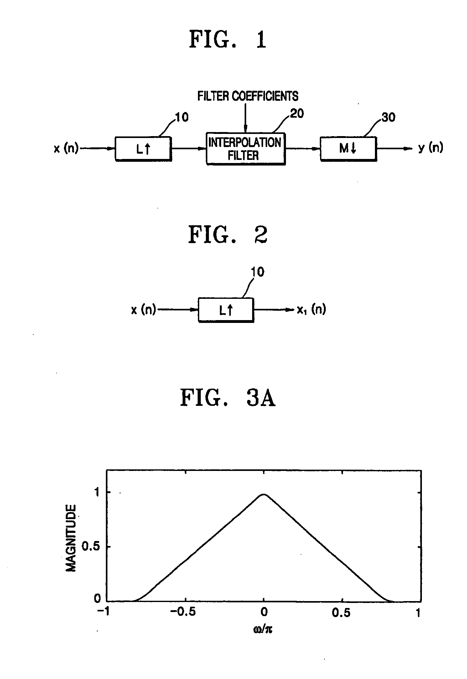
[0036]FIG. 1 is a block diagram illustrating a sampling rate conversion for input video signals according to an embodiment of the present invention. According to a typical sampling conversion technique, the up-sampler 10 performs a zero insertion between the pixels of an input video signal x(n) and outputs an up-sampled video signal. The interpolation filter 20 performs low pass filtering for the up-sampled video signal based on a received filter coefficient, and the down-sampler 30 performs down-sampling for the filtered video signal suitably for a desired resolution.

[0037]FIG. 2 is a block diagram illustrating an L-fold up-sampler in FIG. 1. The L-fold up-sampler ...


PUM


Abstract

A method converts a resolution of video signals, the method including: calculating up-sampling and down-sampling ratios based on a resolution of an input video signal and a desired resolution of an output video signal; calculating a number of filter tabs by multiplying the up-sampling and down-sampling ratios by a number of side lobes; calculating first filter coefficients of a same number of the filter tabs by multiplying a window function by a sinc function; calculating final filter coefficients by subtracting a result of a multiplication of a Gaussian function by a window function from the first filter coefficients, and then normalizing the final filter coefficients; and performing filtering in vertical and horizontal directions based on the final filter coefficients by modifying a sampling rate of an input video signal depending on the up-sampling and down-sampling ratios, to obtain clear video images.

Description

CROSS-REFERENCE TO RELATED APPLICATIONS [0001] This application claims the priority of Korean Patent Application No. 2003-83612, filed on Nov. 24, 2003, in the Korean Intellectual Property Office, the disclosure of which is incorporated herein in its entirety by reference. BACKGROUND OF THE INVENTION [0002] 1. Field of the Invention [0003] The present invention relates to a method of converting input video signals to have a desired resolution and an apparatus using the same, and more particularly, to a method of converting a resolution of video signals, by which the details of the input video may be provided in high definition without additional definition enhancement circuits, such as a peaking circuit, by filtering video signals with optimal filter coefficients being calculated based on a resolution of input and output video signals, and an apparatus using the same. [0004] 2. Description of the Related Art [0005] Since digital display devices, such as a liquid crystal display (LCD...

Claims


Application Information

Patent Timeline
Patent Type & Authority Applications(United States)
IPC IPC(8): H04N5/205G06T3/40H03H17/06H04N7/01
CPCG06T3/4007H03H17/0282H04N7/0135H03H17/0664H04N7/0125H03H17/0657H04N7/01
Inventor LEE, HOYOUNGKIM, CHANGYEONGPARK, DUSIKLEE, SEONGDEOKLUKIN, ALEXEY
Owner SAMSUNG ELECTRONICS CO LTD
Why Eureka
Try Eureka