Hybrid lightguide backlight

a technology of backlighting and lightguide, which is applied in the field of backlighting systems, can solve the problems of lcd manufacturers and television set makers currently not having a model for servicing lcd television backlights, affecting readability, and affecting the uniformity of spatial color of direct-lit displays, so as to achieve enhanced light mixing and mitigate the risks

Inactive Publication Date: 2005-06-23
3M INNOVATIVE PROPERTIES CO
View PDF27 Cites 61 Cited by
  • Summary
  • Abstract
  • Description
  • Claims
  • Application Information

AI Technical Summary

Benefits of technology

[0007] These and other shortcomings of the presently known backlighting systems for large high-performance LCDs are addressed by the inventors of the present disclosure by providing hybrid backlighting systems as disclosed and claimed herein. Such systems may be advantageously used with a variety of devices, including LCD televisions, LCD monitors, point of sale devices, and other suitable devices. The present disclosur

Problems solved by technology

Ambient light illumination is sufficient for some applications, but with most large area and high performance LCDs, ambient light causes glare and is detrimental to readability.
The use of conventional direct-lit backlighting systems, however, has caused some concerns among manufacturers of large LCDs, such as LCD televisions.
In addition, the spatial color uniformity of a direct-lit display suffers as each CCFL ages differently.
Major LCD manufacturers and television set makers currently do not have a model for servicing LCD television backlights that fail in either of these two modes.
Furthermore, light reaching the viewer from m

Method used


Image

  • Hybrid lightguide backlight
  • Hybrid lightguide backlight
  • Hybrid lightguide backlight

Examples


Embodiment Construction

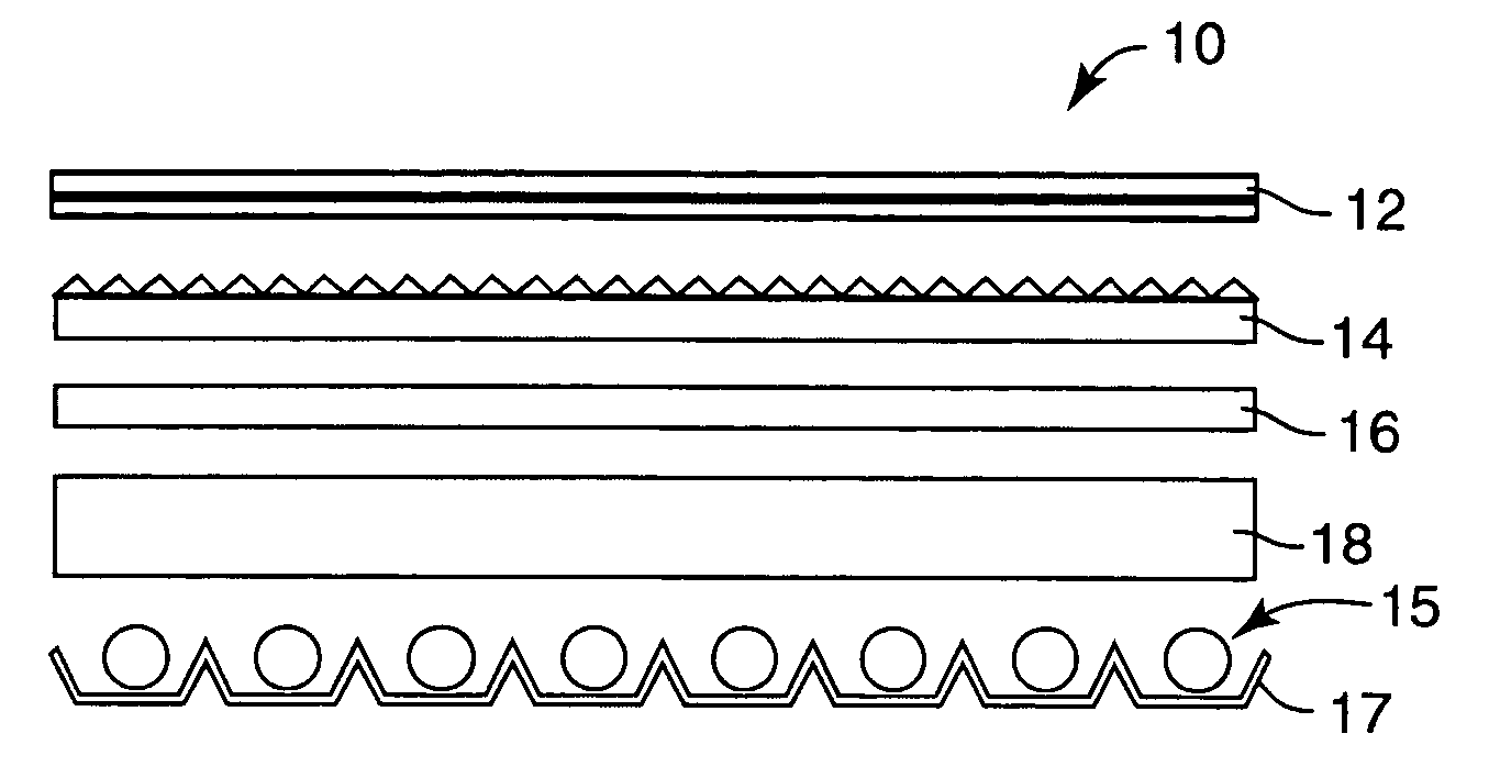
[0022]FIG. 1 illustrates the structure and components of a traditional single-cavity direct-lit backlight 10, such as those presently used in LCD televisions. The traditional backlight 10 includes an array of light bulbs 15, typically CCFLs, and a shaped reflector 17 located behind the array of light bulbs 15 for directing more light toward a viewer. A thick diffuser plate 18 is usually placed over the array of light bulbs 15 to diffuse light from the individual bulbs, e.g., CCFLs, in order to hide them from the viewer. A typical diffuser plate 18 has a large amount of absorption associated with it, as well as a large amount of back scattering, the effects of which grow exponentially if light-recycling enhancement films (described below) are added to the backlight. To further aid in hiding individual light bulbs from the viewer, diffuser plates have been patterned, which resulted in additional losses of light.

[0023] The traditional backlight 10 further includes a thin diffuser shee...


PUM


Abstract

Backlighting systems are disclosed, which include a lightguide with at least one light source optically connected to an edge of the lightguide for supplying light into its interior and a reflective cavity with at least one light source optically connected to the reflective cavity for supplying light into its interior. The reflective cavity may include a first reflector and a second reflector and at least one source may be disposed at an edge of the reflective cavity. Alternatively, the reflective cavity may include a back reflector portion and light sources may be disposed at the back reflector portion.

Description

FIELD OF THE INVENTION [0001] The present disclosure relates to backlighting systems, which may be advantageously used with large high-performance liquid crystal displays. More specifically, the disclosure relates to backlighting systems that include lightguides of different configurations, e.g., edge-lit and direct-lit lightguides. Optionally, the backlighting systems of the present disclosure include various recycling enhancement structures. BACKGROUND OF THE INVENTION [0002] Liquid crystal displays (LCDs) are widely used in electronic display devices, such as computer monitors, handheld devices and televisions. Unlike cathode ray tube (CRT) displays, LCDs do not emit light and, thus, require a separate light source for viewing images formed on such displays. Ambient light illumination is sufficient for some applications, but with most large area and high performance LCDs, ambient light causes glare and is detrimental to readability. Thus, in order to improve readability, most lar...

Claims


Application Information

Patent Timeline
IPC IPC(8): F21V8/00G02B6/00
CPCG02B6/0053G02B6/0076G02B6/0068G02B6/00G02B6/0001
Inventor LAMB, DAVID J.KOTCHICK, KEITH M.GARDINER, MARK E.O'NEILL, MARK B.MARUSHIN, PATRICK H.EPSTEIN, KENNETH A.WATSON, PHILIP E.
Owner 3M INNOVATIVE PROPERTIES CO
Why Eureka
Try Eureka