Supercharge Your Innovation With Domain-Expert AI Agents!

Method and system for real time simultaneous monitoring of logical circuits in a data network

a logical circuit and data network technology, applied in data switching networks, frequency-division multiplexes, instruments, etc., can solve problems such as logical circuits, current methods of determining network circuit failures, and data loss, and achieve the effect of reducing the number of logical circuits and logical circuits

Inactive Publication Date: 2005-06-23
AT&T INTPROP I L P
View PDF97 Cites 61 Cited by
  • Summary
  • Abstract
  • Description
  • Claims
  • Application Information

AI Technical Summary

Benefits of technology

[0009] In accordance with the present invention, the above and other problems are solved by methods for real time simultaneous monitoring of logical circuits in a data network. According to one method, trap data is received for a group of logical circuits in the data network. The trap data may include current status information for each of the circuits in the logical circuit group. Next, based on the trap data, a logical identifier associated with each of the logical circuits in the group is identified. Then, each of the logical identifiers is associated with customer data stored in a database. The customer data includes one or more logical identifiers associated with a customer identification. Finally, the current status information for one or more logical circuits is displayed along with the corresponding customer identification.

Problems solved by technology

Periodically, failures may occur to the trunk circuits or the NNIs of network circuits in large-scale networks causing lost data.
Current methods of determining network circuit failures, however, suffer from several drawbacks.
One drawback is that logical circuits must be identified one at a time using the logical element module to isolate failures.
The individual identification of logical circuits is time intensive and results in dropped data packets or cells until the each of the logical circuits is isolated and repaired.
Furthermore troubleshooting the physical circuit often requires taking the network circuit out of service to perform testing, thus increasing the downtime and loss of data in the network circuit.

Method used


Image

  • Method and system for real time simultaneous monitoring of logical circuits in a data network
  • Method and system for real time simultaneous monitoring of logical circuits in a data network
  • Method and system for real time simultaneous monitoring of logical circuits in a data network

Examples


Embodiment Construction

[0018] Embodiments of the present invention provide for a method and system for real-time simultaneous monitoring of logical circuits in a data network. In the following detailed description, references are made to the accompanying drawings that form a part hereof, and in which are shown by way of illustration specific embodiments or examples. Referring now to the drawings, in which like numerals represent like elements through the several figures, aspects of the present invention and the exemplary operating environment will be described.

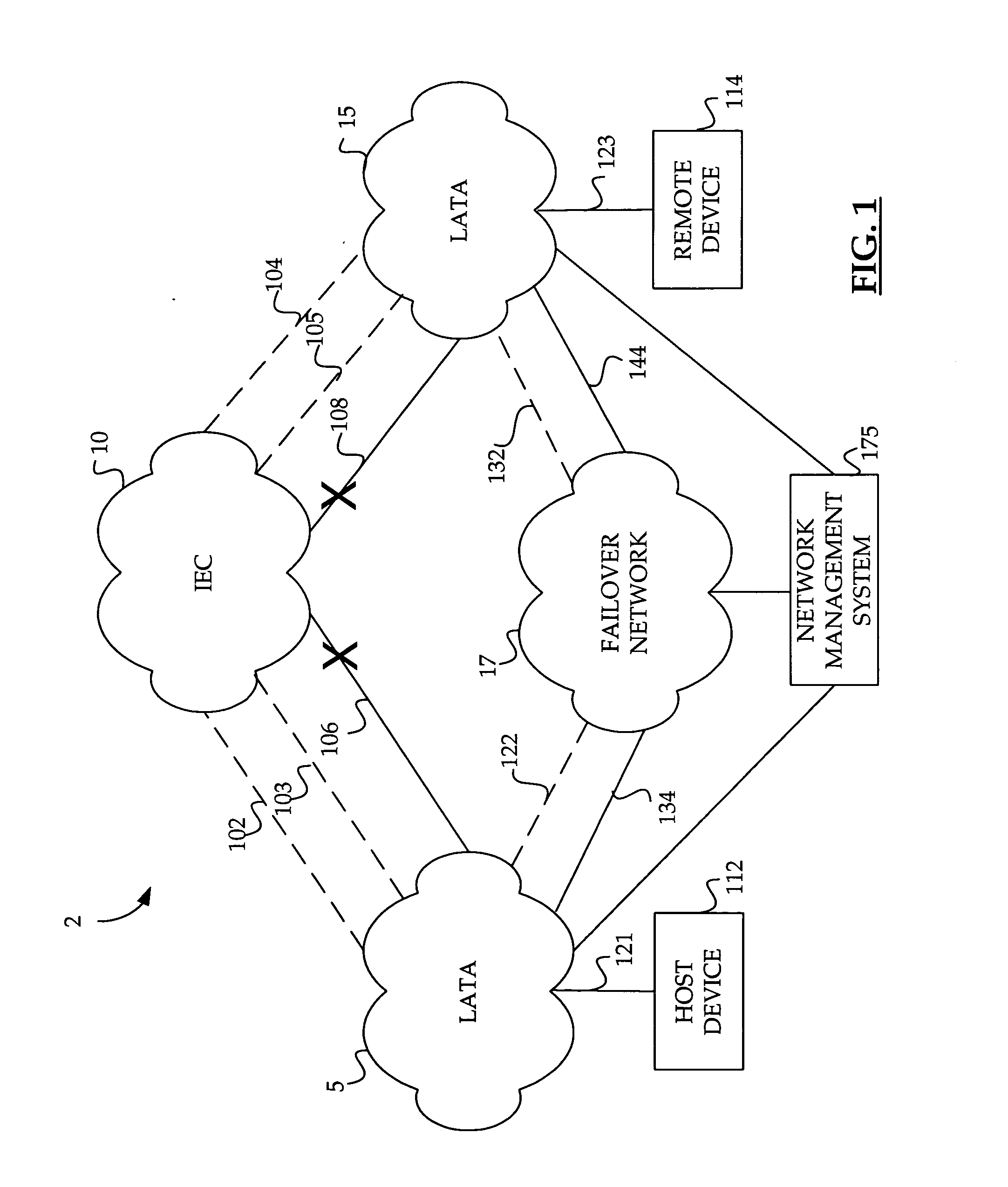
[0019] Embodiments of the present invention may be generally employed in a data network 2 as shown in FIG. 1. The data network 2 includes local access and transport areas (“LATAs”) 5 and 15 which are connected by an Inter-Exchange Carrier (“IEC”) 10. It should be understood that the LATAs 5 and 15 may be operated by a commonly owned Local Exchange Carrier (“LEC”). It should be further understood that the IEC 10 may include one or more data networks...


PUM


Abstract

A method and computer system are provided for real time simultaneous monitoring of logical circuits in a data network. A network management module receives trap data for a group of logical circuits in the data network. The trap data may include current status information for each of the circuits in the logical circuit group. Next, based on the trap data, a logical identifier associated with each of the logical circuits in the group is identified. Then, each of the logical identifiers is associated with customer data stored in a database. The customer data includes one or more logical identifiers associated with a customer identification. Finally, the current status information for the logical circuit group is displayed along with the corresponding customer identification.

Description

CROSS-REFERENCE TO RELATED APPLICATIONS [0001] The present application is related to U.S. patent application Ser. No. 10 / 348,077, entitled “Method and System for Obtaining Logical Performance Data for a Circuit in a Data Network,” filed on Jan. 21, 2003, and U.S. patent application Ser. No. 10 / 348,592, entitled “Method and System for Provisioning and Maintaining a Circuit in a Data Network,” filed on Jan. 21, 2003. This application is also related to and filed concurrently with U.S. patent application Ser. No. ______, entitled “Method And System For Providing A Failover Circuit For Rerouting Logical Circuit Data In A Data Network,” bearing attorney docket number 60027.0337US01 / BS030233, filed on Dec. 23, 2003, U.S. patent application Ser. No. ______, entitled “Method And System For Utilizing A Logical Failover Circuit For Rerouting Data Between Data Networks,” bearing attorney docket number 60027.0338US01 / 030236, filed on Dec. 23, 2003, U.S. patent application Ser. No. ______, entit...

Claims


Application Information

Patent Timeline
Patent Type & Authority Applications(United States)
IPC IPC(8): H04L1/00H04L12/24H04L12/26
CPCH04L43/0817H04L41/0233
Inventor TAYLOR, WILLIAMMASSENGILL, DAVIDHOLLINGSWORTH, JOHN
Owner AT&T INTPROP I L P
Features
  • R&D
  • Intellectual Property
  • Life Sciences
  • Materials
  • Tech Scout
  • Unparalleled Data Quality
  • Higher Quality Content
  • 60% Fewer Hallucinations
Learn More