Stackable routers employing a routing protocol

US20050135357A1Active Publication Date: 2005-06-23VALTRUS INNOVATIONS LTD

Image

  • Stackable routers employing a routing protocol
  • Stackable routers employing a routing protocol
  • Stackable routers employing a routing protocol

Examples


Embodiment Construction

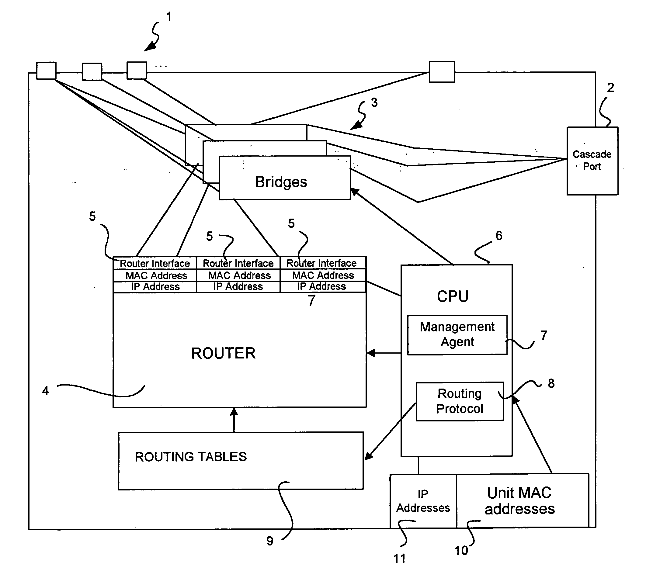
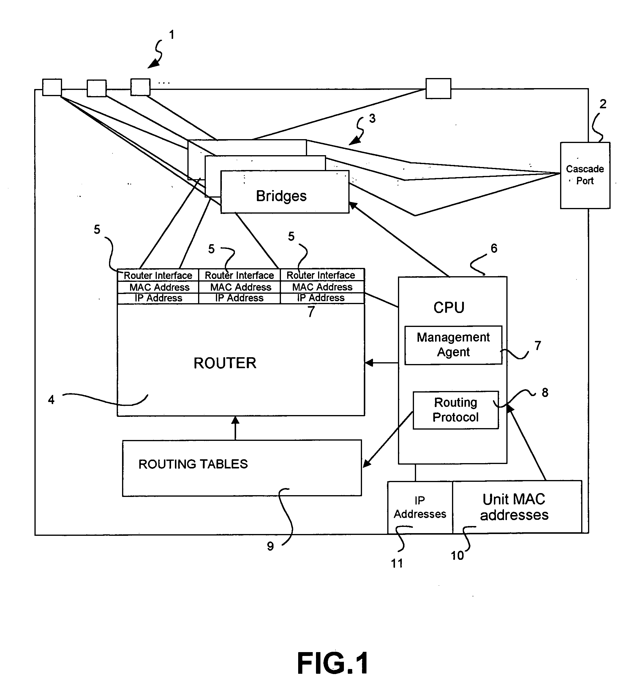
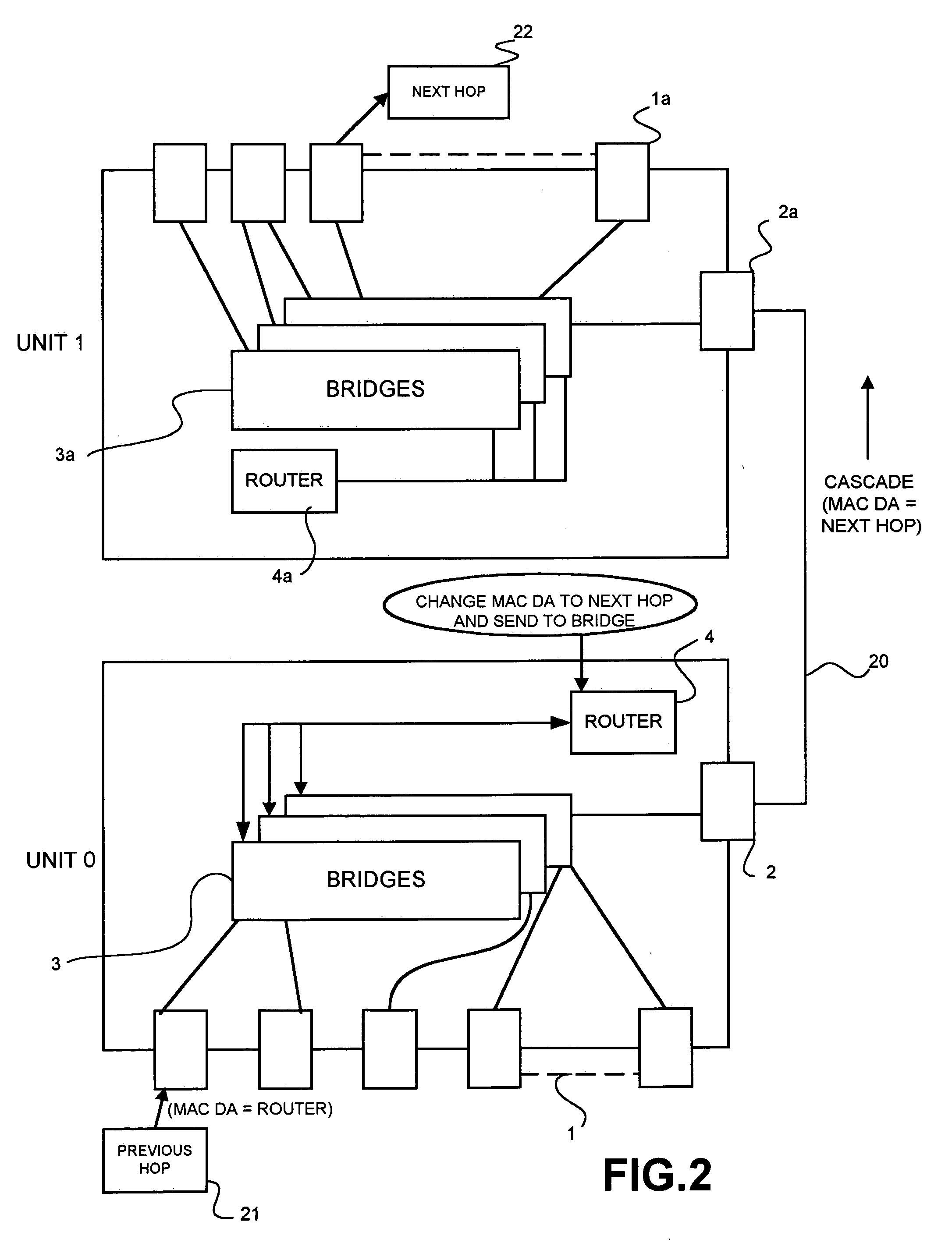
[0045]FIG. 1 illustrates, in conjunction with FIG. 3 to be described later, a network unit which is intended for use in a resilient stack according, for example, to the schemes shown in FIG. 2. A unit as described for example in FIGS. 1 and 3 is an example of a unit which is to employ a stackable routing protocol according to the invention.

[0046] The unit has a multiplicity of ordinary or ‘front panel’ ports 1 and at least one ‘cascade port’2. The ‘cascade port’ may be a separate dedicated connection between the units or it may be one of the front panel ports dedicated to perform ‘cascade’ functionality. The unit includes at least one and usually a multiplicity of ‘hardware’ bridges, or ‘layer 2’ switches 3. Each port 1 is connected to at least one of the bridges 3 and the (or each) cascade port is connected to all the bridges, or to a ‘logical’ port connected to all the bridges. The unit includes a router 4 which has at least two, and in the illustrated example three, router inter...


PUM


Abstract

A stack of network routers is composed of at least one (elected) master unit and one or more slave units each capable of running a routing protocol. Only the master unit runs the entire routing protocol at a given time. It forwards direct update messages via a transmission control protocol to each of the slave units. These direct update messages may include specific packet formats for the protocol state machinery where such machinery is required by the routing protocol, e.g. the interface state machine and the neighbor state machine for the OSPF protocol, and for the net databases, e.g. the link state databases for the OSPF protocol, in each of the slave units. Each slave unit may run its protocol state machinery (where provided) based purely on the direct update messages received from the master. The synchronisation of the net databases may be based on snooping net update packets and a comparison of the information received thereby with verification data messages sent from the master unit. The synchronization allows the running of the routing protocol on multiple physical routers in a stack without requiring the overhead of a back-up unit that would not perform routing unless a master router unit became unavailable.

Description

FIELD OF THE INVENTION [0001] This invention relates to packet-based communication systems which employ addressed data packets for the conveyance of information between units in the system and more particularly to the ‘stacking’ or ‘cascading’ of routing entities so that they appear to constitute a single logical routing entity. The invention specifically concerns the adaptation of a routing protocol, particularly the OSPF (open shortest path first) protocol in a stack or cascade of routers. BACKGROUND TO THE INVENTION [0002] Network units such as switches which include a multiplicity of ports for connection to other units or users are commonly made with a fixed number of ports in order to achieve efficiency of manufacture. It is known to ‘stack’ or ‘cascade’ such units by means of interconnection and a common control or management system to constitute a single switching or routing entity from a multiplicity of individual units. A particular example is disclosed in U.S. patent appli...

Claims


Application Information

Patent Timeline
23 Jun 2005
Publication
US20050135357A1
IPC
H04L12/56
CPC
H04L45/583; H04L45/00
Inventors
RIEGEL, JANE A.; TULACZ, JACEK A.