High resolution synthesizer with improved signal purity

a high-resolution, signal-purity technology, applied in the direction of generating/distributing signals, instruments, digital transmission, etc., can solve the problems of consuming too much power, circuitry needed to operate a dds signal generator for high spectral purity, and general inaccessibility of circuitry to generate data stream into the da

Active Publication Date: 2005-06-23
TERADYNE
View PDF18 Cites 26 Cited by
  • Summary
  • Abstract
  • Description
  • Claims
  • Application Information

AI Technical Summary

Benefits of technology

[0018] With the foregoing background in mind, it is an object to provide an improved DDS signal generator.
[0019] The forgoing and other objects are achieved in a DDS signal generator with a high sampling rate DAC fed by a circuit that interleaves a plurality of data streams. In the preferred embodiment, the data streams are generated by relatively inexpensive ci

Problems solved by technology

However, as DACs with faster sampling rates become available, there are limitations on the availability of circuitry that can generate the data stream into the DAC.
The circuitry needed to

Method used


Image

  • High resolution synthesizer with improved signal purity
  • High resolution synthesizer with improved signal purity
  • High resolution synthesizer with improved signal purity

Examples


Embodiment Construction

[0030] This invention is not limited in its application to the details of construction and the arrangement of components set forth in the following description or illustrated in the drawings. The invention is capable of other embodiments and of being practiced or of being carried out in various ways. Also, the phraseology and terminology used herein is for the purpose of description and should not be regarded as limiting. The use of “including,”“comprising,” or “having,”“containing”, “involving”, and variations thereof herein, is meant to encompass the items listed thereafter and equivalents thereof as well as additional items.

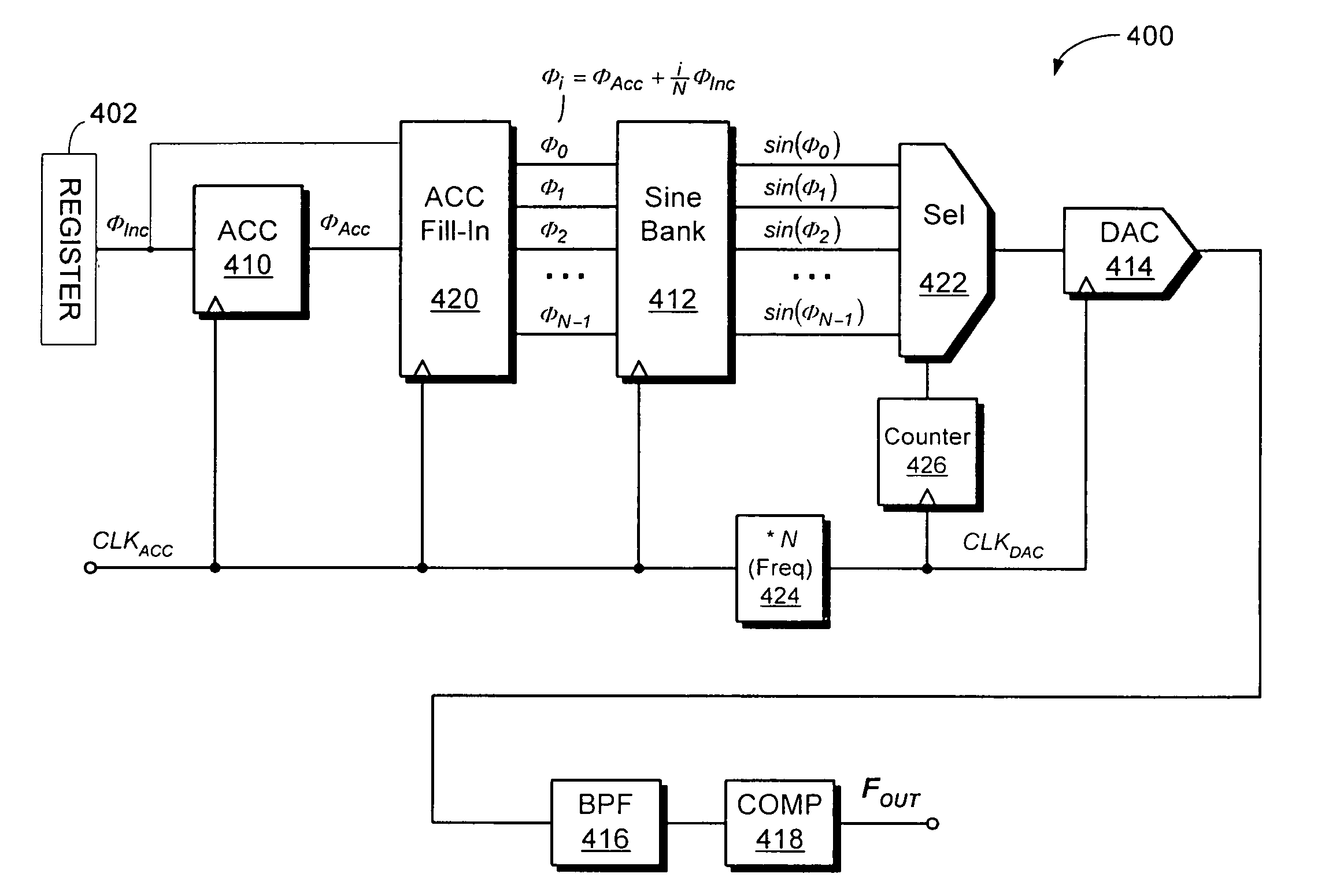
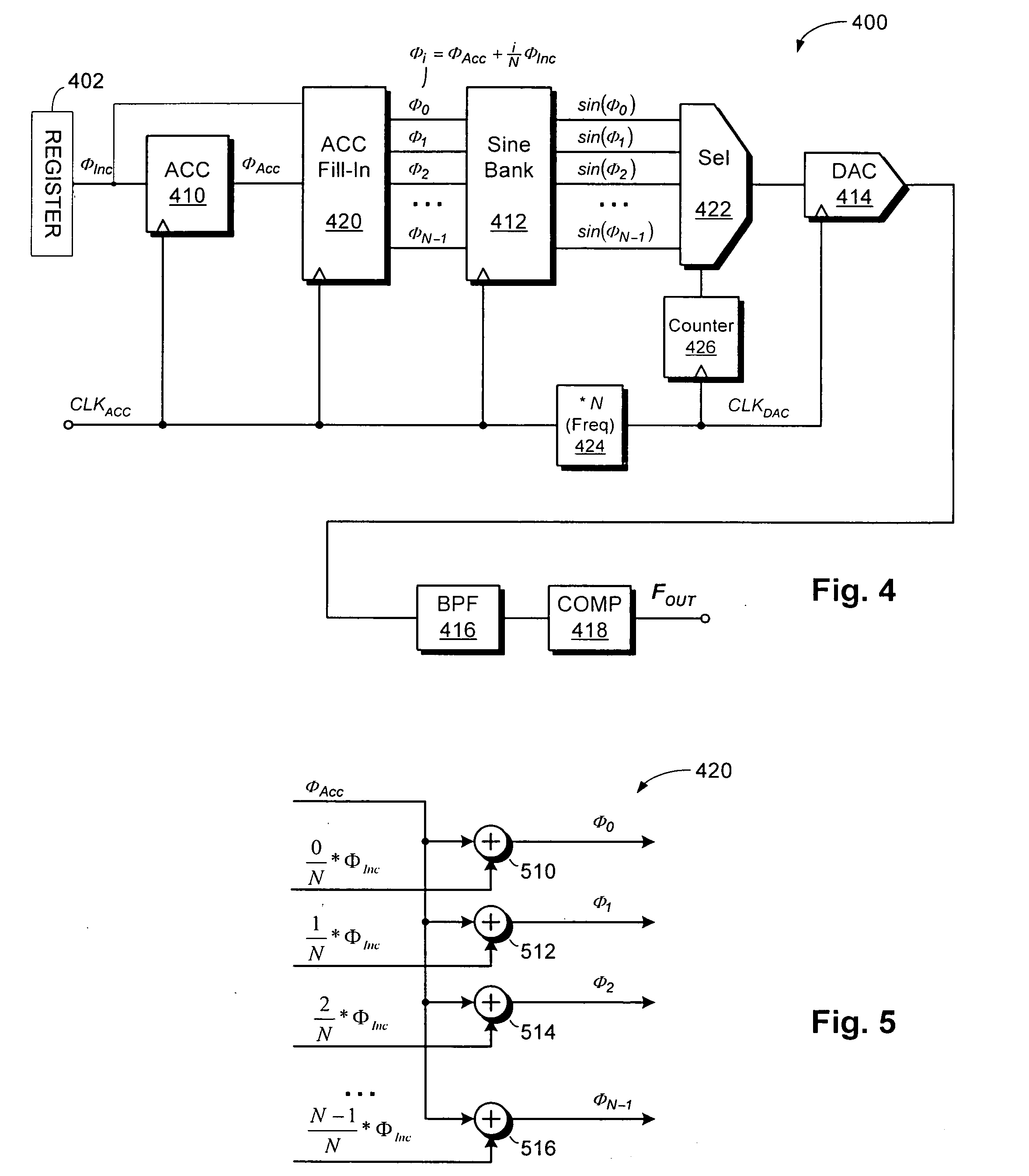
[0031]FIG. 4 shows a synthesizer 400 used to generate a low jitter digital clock. Synthesizer 400 uses a modified form of direct digital synthesis.

[0032] As in the prior art, synthesizer 400 is clocked by a clock CLKACC. Register 402 stores a value of ΦInc. For each cycle of clock CLKACC, the value stored in accumulator 410 increases by the value of ΦInc sto...


PUM


Abstract

An automatic test system using a DDS signal generator to create a signal with high spectral purity or a low jitter digital clock. The low jitter clock has variable frequency and is programmed to control other test functions, such as the generation of arbitrary waveforms. The DDS uses a high resolution, high sampling rate DAC to generate a sine wave that is converted to a digital clock. The architecture of the DDS signal generator allows low cost CMOS circuitry to be used to generate the data stream that feeds the high sample rate DAC.

Description

[0001] This invention relates generally to signal generation and more specifically to generation of periodic signals with high purity. BACKGROUND OF INVENTION [0002] Direct Digital Synthesis (“DDS”) is a technique used to generate periodic signals where control over one or more signal properties is desired. Analog signals can be generated with the period and the wave shape controlled through DDS. [0003]FIG. 1 shows a traditional DDS architecture with (DDS) 100 being used to generate a sine wave that is then converted to a two-valued clock. The DDS 100 receives an accumulator clock CLKACC and a digital input signal ΦInc indicating a phase increment. The DDS outputs an analog signal FOUT. The frequency of FOUT can be set by varying the frequency of CLKACC and / or varying the phase increment ΦInc. [0004] In operation, accumulator 110 produces a new output value ΦAcc on each cycle of clock CLKACC. To produce each new value, the accumulator 110 adds ΦInc to its current contents. FIG. 2 sh...

Claims


Application Information

Patent Timeline
IPC IPC(8): G06F1/02G01R31/3183G06F1/03
CPCG06F1/08G06F1/0328
Inventor MESSIER, JASON
Owner TERADYNE
Why Eureka
Try Eureka