Device and method for coating serpentine fluorescent lamps

Inactive Publication Date: 2005-06-23
LCD LIGHTING
View PDF9 Cites 3 Cited by
  • Summary
  • Abstract
  • Description
  • Claims
  • Application Information

AI Technical Summary

Benefits of technology

[0009] It is an advantage of the present invention that there is little waste of the coating material.
[0010] It is another advantage of the present invention that a reflective material can be placed on circumferential portion of a serpentine tube.
[0011] It is a further advantage of the present invention that a phosphor coating can easily be applied to a serpentine tube without utilizing the force of gravity to

Problems solved by technology
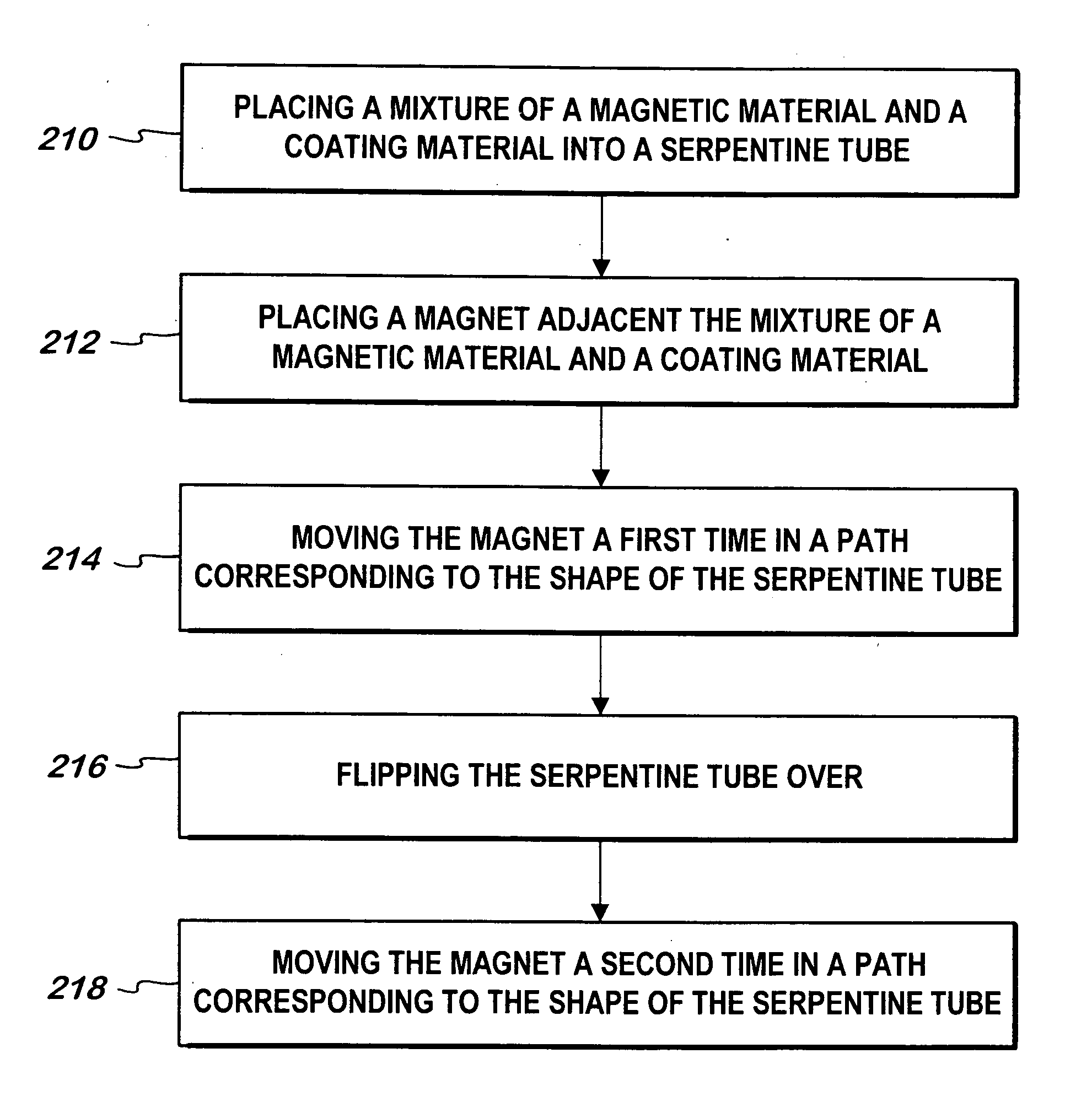
However, there are many lamps used for special applications, which require unique or unusual configurations.
It is often diffic

Method used


Image

  • Device and method for coating serpentine fluorescent lamps
  • Device and method for coating serpentine fluorescent lamps
  • Device and method for coating serpentine fluorescent lamps

Examples


Example

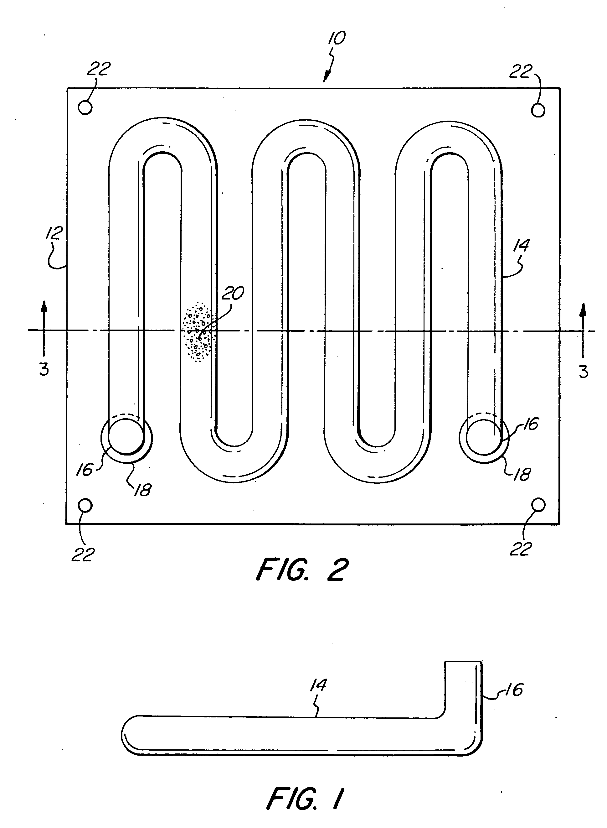
[0024]FIG. 1 illustrates a serpentine tube 14 having a leg 16 used in forming a fluorescent lamp. The tube 14 may be made of any type of glass required for the particular application. In the manufacture of a fluorescent lamp, a phosphor or reflective coating is ordinarily applied to the interior surface of the lamp. The phosphor or reflective material is generally suspended or in solution in a liquid during coating, and then permitted to dry leaving the phosphor or reflective coating. Electrodes are placed at either end of the lamp so that when the electrodes are energized, an electric arc between the electrodes causes the phosphor coating to radiate. The reflective coating aids in directing and concentrating the illumination in a predetermined direction. The electrodes are usually placed at the ends of the lamp and mounted on legs 16. The configuration of the serpentine lamp 14 and the placement of legs 16 make it particularly difficult to coat the interior surface of the serpentin...


PUM

PropertyMeasurementUnit
Shapeaaaaaaaaaa
Abrasiveaaaaaaaaaa
Circumferenceaaaaaaaaaa

Abstract

A serpentine tube used in the manufacture of a fluorescent lamp is coated with a reflective or phosphor material. A magnetic material and coating material slurry is placed within one end of a serpentine glass tube. A magnet is placed adjacent the magnetic material and coating material slurry and is moved in a path conforming to the shape of the serpentine tube. The magnet causes the magnetic material and coating material slurry to travel along therewith, coating a portion of the interior surface of the serpentine tube with a reflective, phosphor, or other material. In another embodiment of the invention, abrasive magnetic material is placed within the serpentine lamp for removing a previously coated material resulting in an aperture being formed. The present invention is particularly suited to the manufacture of serpentine fluorescent lamps that are used to illuminate flat panel displays.

Description

FIELD OF THE INVENTION [0001] The present invention relates in general to the manufacture of serpentine fluorescent lamps, and more particularly to the coating of a serpentine fluorescent lamp with a material such as a reflective coating or phosphor material. BACKGROUND OF THE INVENTION [0002] Fluorescent lamps are widely used in many lighting applications. In the manufacture of a fluorescent lamp, a phosphor coating is often required to be placed on the interior surface of the lamp. Generally, fluorescent lamps are made from straight glass tubes. The interior surface of the glass tube is often easily coated by placing within the glass tube a liquid phosphor material and tilting or rotating the glass tube. Other coating techniques have also been used. For example, one end of the tube may also be immersed in a quantity of liquid phosphor and a vacuum used to draw the liquid phosphor up the interior of the tube, and then removing the vacuum causing the liquid phosphor to drain out of ...

Claims


Application Information

Patent Timeline
IPC IPC(8): H01J9/22
CPCH01J9/20H01J61/44H01J61/307Y10S118/10
Inventor SEDENSZKI, ISTVANKOVACS, GEORGE
Owner LCD LIGHTING
Why Eureka
Try Eureka