Sequence-based positioning technique

a positioning technique and sequence technology, applied in the field of positioning techniques, can solve the problems of absurd ideas and store owners who are not interested in accurately determining the most recent locations, and achieve the effects of reducing uncertainty, reducing uncertainty, and reducing uncertainty

Active Publication Date: 2005-06-23
AIRISTA FLOW INC +1
View PDF3 Cites 84 Cited by
  • Summary
  • Abstract
  • Description
  • Claims
  • Application Information

AI Technical Summary

Benefits of technology

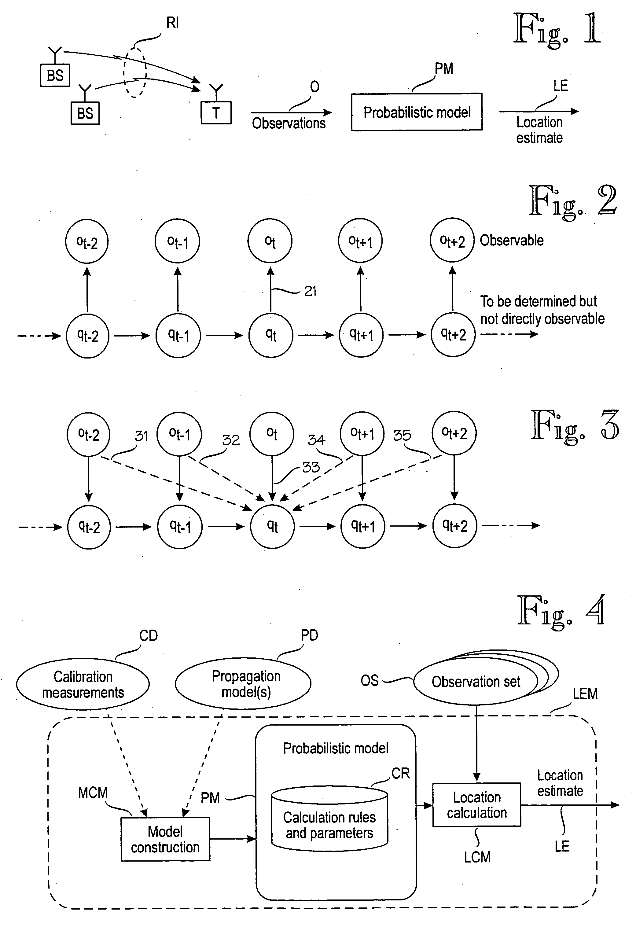
[0009] The invention is based on the idea of using the target device's future observations to reduce the uncertainty concerning the target device's location. At first sight, this idea sounds absurd because at any given time, the target device's future observations are not known. Thus an apparent limitation of the invention is that it is only applicable to observations that do have at least one future. observation. In other words, the invention cannot directly reduce the uncertainty concerning the target device's most recent observation, but the invention is partially based on the surprising discovery that there are many applications that benefit from reducing the uncertainty concerning the target device's past observations. For example, the invention can be used to track customers' paths in a shop by attaching suitable target devices to shopping carts. Such information can be useful to design the placement of goods within the shop. Assume that a customer's path begins and ends at the points where the customer takes and leaves, respectively, the shopping cart. Thus the store owner is not interested in determining the most recent locations accurately because all paths end at the checkout points. On the other hand, the store owner is interested in determining the customers' paths inside the shop, and the most recent observations can be used to reduce the uncertainty concerning prior locations within the shop.

Problems solved by technology

At first sight, this idea sounds absurd because at any given time, the target device's future observations are not known.
Thus the store owner is not interested in determining the most recent locations accurately because all paths end at the checkout points.

Method used


Image

  • Sequence-based positioning technique
  • Sequence-based positioning technique
  • Sequence-based positioning technique

Examples


performance example

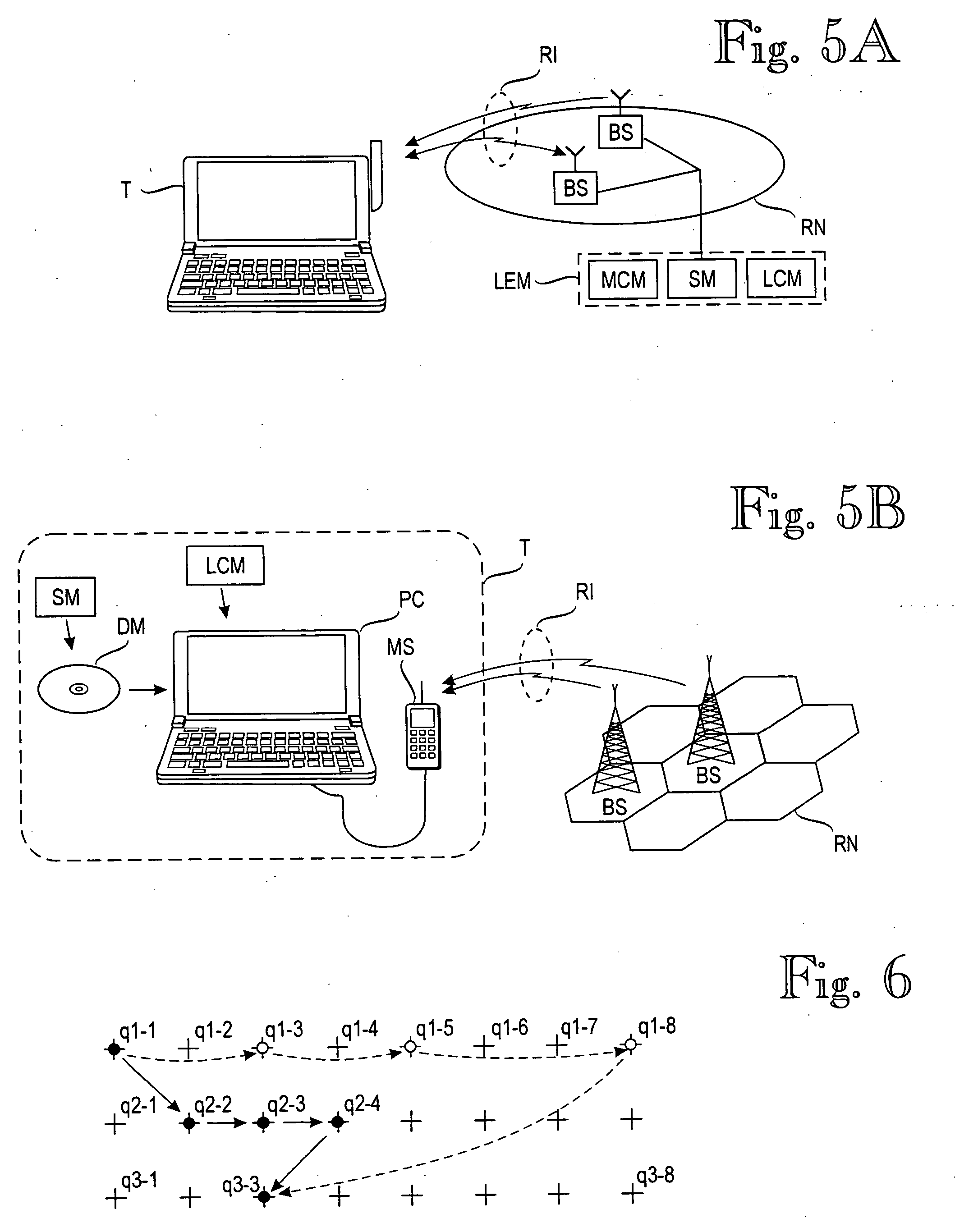
[0050] The following detailed calculations demonstrate how, at least in some situations, the invention can improve positioning accuracy even in real-time positioning. In some situations, the improvement may be significant. The following table 1 contains observation probabilities for locations A to F at (discrete) times t=1 to 5. Bold values show the observation probabilities of the real path A,B,D,E,F at each time step. Note that although the real location at time t=3 is D, location C has a higher observation probability. Hence, positioning based only on the current observation probabilities would fail at that point. Table 2 contains transition probabilities between locations A to F. Tables 3 to 5 contain. normalized calculation results for forward, backward. and two-way recursions (equations 3, 4 and 2), respectively. Again, probabilities of real locations at each time step are shown in bold text. Table 6 shows probabilities for locations A to F at time t=3.

TABLE 1observation pro...


PUM


Abstract

A target device's location is estimated by a location estimation module (LEM) that comprises a probabilistic model (PM) for a plurality of sample points, each of which comprises a sample location and an expected distribution of signal values at that sample point. The location estimation module (LEM) makes a sequence (OS) of observations on, n=1, 2, 3 . . . , of signal values. Each observation corresponds to a respective location qn along the target device's path. The sequence of observations and the respective location constitute a hidden Markov model. The module estimates the target device's location qn based on the probabilistic model (PM) and the sequence of observations, wherein the sequence of observations comprises one or more future observations on+m for which m is a positive integer. In other words, the target device's location is estimated, at least partially, based on knowledge of its future.

Description

[0001] This is a continuation of International Application No. PCT / FI03 / 00412, filed May 27, 2003, which claims priority from Finnish Application No. 20021043, filed May 31, 2002, the contents of both of which are incorporated herein by reference.BACKGROUND OF THE INVENTION [0002] The invention relates generally to a positioning technique in which a target device's location is estimated on the basis of a sequence of observations on the target device's wireless communication environment. FIG. 1 schematically illustrates an example of such a positioning technique. A target device T communicates via base stations BS via a radio interface RI. In this example, the communication is assumed to be radio communication. The target device T. observes signal values at the radio interface RI. The observations O are applied to a probabilistic model PM that models the target device's wireless communication environment and produces a location estimate LE. As used herein, a target device is a device...

Claims


Application Information

Patent Timeline
Patent Type & Authority Applications(United States)
IPC IPC(8): G01S5/02H04L12/56H04W64/00
CPCH04W64/00G01S5/0252G01S5/02521
Inventor MISIKANGAS, PAULIMYLLYMAKI, PETRI
Owner AIRISTA FLOW INC
Why Eureka
Try Eureka