
Golf Club Striking Plate wtih Variable Thickness

a golf club and variable thickness technology, applied in the field of golf club striking plates, can solve the problems of golf clubs, golf clubs, golf equipment, etc., and achieve the effects of less golf club head weight, less overall thickness of striking plates, and more compliance during impa

Inactive Publication Date: 2005-06-23
TOPGOLF CALLAWAY BRANDS CORP
View PDF8 Cites 37 Cited by
  • Summary
  • Abstract
  • Description
  • Claims
  • Application Information

AI Technical Summary

Benefits of technology

[0014] The present invention is directed at a striking plate for a golf club head that is contoured according to the probability of impact with a golf ball in order to lessen the overall thickness of the striking plate, and thus lessen the weight of the golf club head. Further, the striking plate has regions of varying thickness that allow for more compliance during impact with a golf ball.

Problems solved by technology

However, thinning the striking plate too much may lead to failure of the golf club.
In the relatively thin striking plates of hollow metal woods and cavity-back irons, these forces tend to produce large internal stresses in the striking plate.
These internal stresses often cause catastrophic material cracking which leads to failure of the club head.
Computational and experimental studies on hollow metal woods and cavity-backed irons have demonstrated that such catastrophic material cracking most often occurs at impact points on the striking plate.
However, the addition of such a large amount of material to a striking plate generally adversely affects the performance of the golf club.
However, the prior art has failed to design a striking plate or face plate that varies the thickness according to predicted golf ball impact points on the striking plate.

Method used


Image

  • Golf Club Striking Plate wtih Variable Thickness
  • Golf Club Striking Plate wtih Variable Thickness
  • Golf Club Striking Plate wtih Variable Thickness

Examples


Embodiment Construction

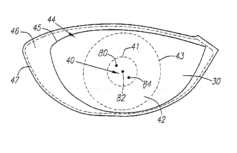
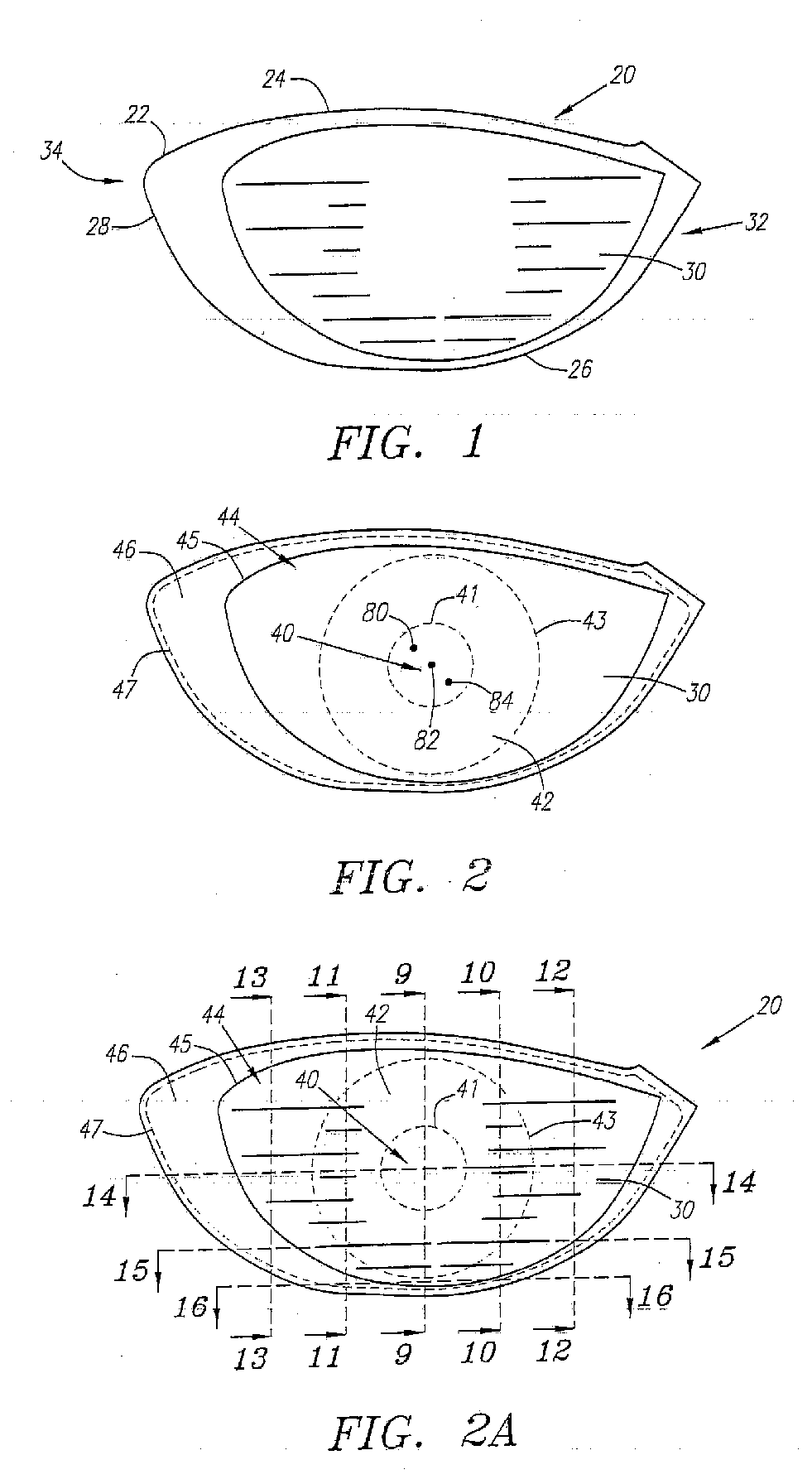
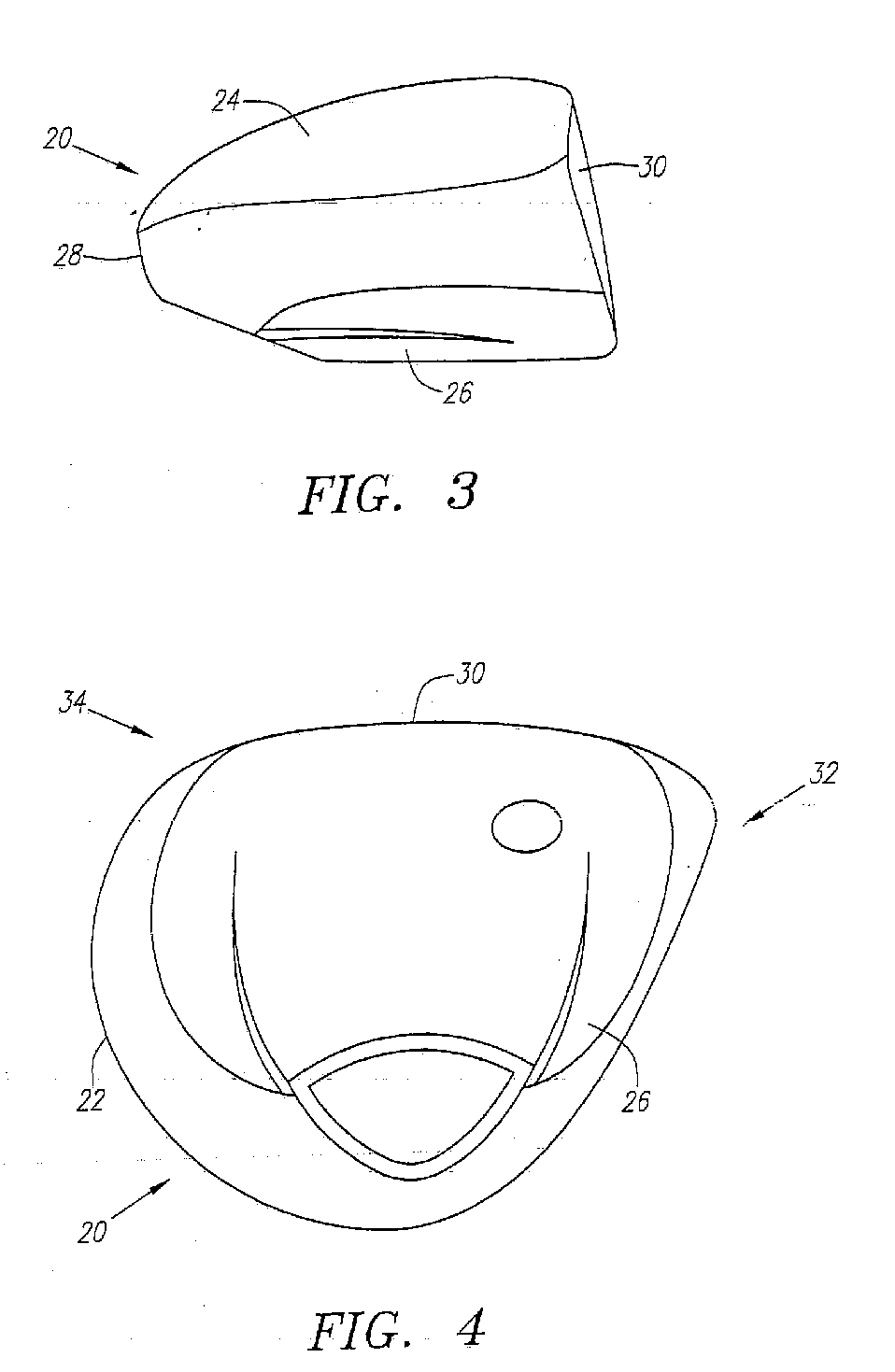
[0037] As shown in FIGS. 1-8, a golf club head is generally designated 20. The golf club head 20 has a body 22 with a crown 24, a sole 26, a ribbon 28 and a striking plate 30. The striking plate 30 generally extends from a heel end 32 to a toe end 34 of the front of the golf club head 20. The body 22 preferably has an internal hosel 36 for receiving the tip end of a shaft, not shown, through an aperture 38. The golf club head has a body 22 that is preferably composed of a metal material such as titanium, titanium alloy, stainless steel, or the like, and is most preferably composed of a forged titanium material. The body 22 preferably has a large volume, most preferably greater than 300 cubic centimeters, and is most preferably 350 cubic centimeters. The body 22 preferably weighs no more than 215 grams, and most preferably weighs between 180 and 205 grams. The body 22 has a hollow interior 23.

[0038] The striking plate 30 is partitioned into a plurality of regions 40, 42, 44 and 46, ...


PUM

PropertyMeasurementUnit
thicknessaaaaaaaaaa
volumeaaaaaaaaaa
areaaaaaaaaaaa

Abstract

A golf club head having a striking plate with regions of varying thickness is disclosed herein. A central region has a first thickness range that is thicker than the thickness range of any of the other regions. The thickness of the regions decreases outward from the center. The striking plate may be used on a fairway wood-type golf club head or a driver-type golf club head. The striking plate is preferably composed of steel or titanium.

Description

CROSS REFERENCES TO RELATED APPLICATIONS [0001] The present application is a continuation of U.S. patent application Ser. No. 10 / 605,291, which was filed on Sep. 19, 2003, which is a continuation of U.S. patent application Ser. No. 10 / 063,927, which was filed on May 24, 2002, now U.S. Pat. No. 6,623,377, which is a continuation of U.S. patent application Ser. No. 09 / 606,809, which was filed on Jun. 28, 2000, now U.S. Pat. No. 6,398,666, which is a continuation-in-part of U.S. patent application Ser. No. 09 / 481,167, which was filed on Jan. 12, 2000, now U.S. Pat. No. 6,368,234, which is a continuation-in-part of U.S. patent application Ser. No. 09 / 431,982, which was filed on Nov. 1, 1999, now U.S. Pat. No. 6,354,962.BACKGROUND OF THE INVENTION [0002] 1. Field of the Invention [0003] The present invention relates to a golf club striking plate. More specifically, the present invention relates to a golf ball striking plate having a variable thickness. [0004] 2. Description of the Relate...

Claims


Application Information

Patent Timeline
Patent Type & Authority Applications(United States)
IPC IPC(8): A63B53/02A63B53/04A63B53/06A63B53/08B21J5/00B21K17/00C22F1/18C23F1/00C23F1/26
CPCA63B53/02A63B2053/0462A63B53/0466A63B53/08A63B2053/0408A63B2053/0412A63B2053/0416A63B2053/0441A63B2053/0458B21J5/00B21K17/00C22F1/183C23F1/00C23F1/26A63B2053/0433A63B2053/045A63B53/04A63B60/00A63B53/0412A63B53/045A63B53/0462A63B53/0441A63B53/0458A63B53/0408A63B53/0416A63B53/0433
Inventor EVANS, D. CLAYTONGALLOWAY, J. ANDREW
Owner TOPGOLF CALLAWAY BRANDS CORP
Learn More