Method and apparatus for spinal distraction

a technology of spinal cord and apparatus, applied in the field of spinal cord distraction, can solve the problems of affecting the productivity of the workforce and health care expense, affecting the success of 70% of the procedures performed, and not restoring normal physiological disc function, etc., and achieves the effects of less immediate trauma, blood loss, and easy adaptation to other situations

Active Publication Date: 2005-06-23
MIS IP HLDG LLC
View PDF99 Cites 184 Cited by
  • Summary
  • Abstract
  • Description
  • Claims
  • Application Information

AI Technical Summary

Benefits of technology

[0024] Moreover, in accordance with the techniques and surgical tool sets, and in particular the cutters and extraction tool configurations disclosed herein, a substantially greater amount (volume) of intradiscal material e.g., nucleus pulposus and cartilage, in comparison with other discectomy procedures in practice, may be removed, as needed. In particular, the instrumentation systems and techniques embodied in the present invention more effectively, with less immediate trauma, and without residual negative physiological impacts that may occur as a result of invasion of the annulus, prepare an inter-vertebral motion segment for subsequent receipt of therapeutic procedures, and enables axial placement of implants close to and in alignment with the human spine's physiological center of rotation.
[0025] Other specific advantages over current practice include: the patient is in a prone position that is easily adaptable to other posterior instrumentation; blood loss is minimal soft tissue structures, e.g., veins, arteries, nerves are preserved, and substantially less surgical and anesthesia time are required compared with conventional procedures.
[0028] In accordance with a further aspect of the present invention, there is provided a method of increasing the distance between a first vertebral body and a second vertebral body. The method comprises the steps of providing an internal distraction device having an elongate body, a first threaded surface on a proximal portion of the body and a second threaded surface on a distal portion of the body. The first threaded surface is engaged with the first vertebral body, and the second threaded surface is engaged with the second vertebral body. The distraction device is rotated to increase the distance between the first vertebral body and the second vertebral body.

Problems solved by technology

Chronic lower back pain is a primary cause of lost work days in the United States, and as such is a significant factor affecting both workforce productivity and health care expense.
In addition, statistics show that only about 70% of these procedures performed will be successful in achieving this end.
Surgical procedures, such as spinal fusion and discectomy, may alleviate pain, but do not restore normal physiological disc function.
With age, the water and protein content of the body's cartilage changes resulting in thinner, more fragile cartilage.
Hence, the spinal discs and the facet joints that stack the vertebrae, both of which are partly composed of cartilage, are subject to similar degradation over time.
Weakening of the annulus may lead to disc bulging and herniation, i.e., the nucleus pulposus or softer portion of the disc can rupture through the annulus and abut the spinal cord or its nerves as they exit the bony spinal column.
When disc herniation occurs, the rupture of the nucleus pulposus the annulus fibrosis may irritate adjacent nervous tissue, causing local pain, or discogenic pain, in the affected area.

Method used


Image

  • Method and apparatus for spinal distraction
  • Method and apparatus for spinal distraction
  • Method and apparatus for spinal distraction

Examples


Embodiment Construction

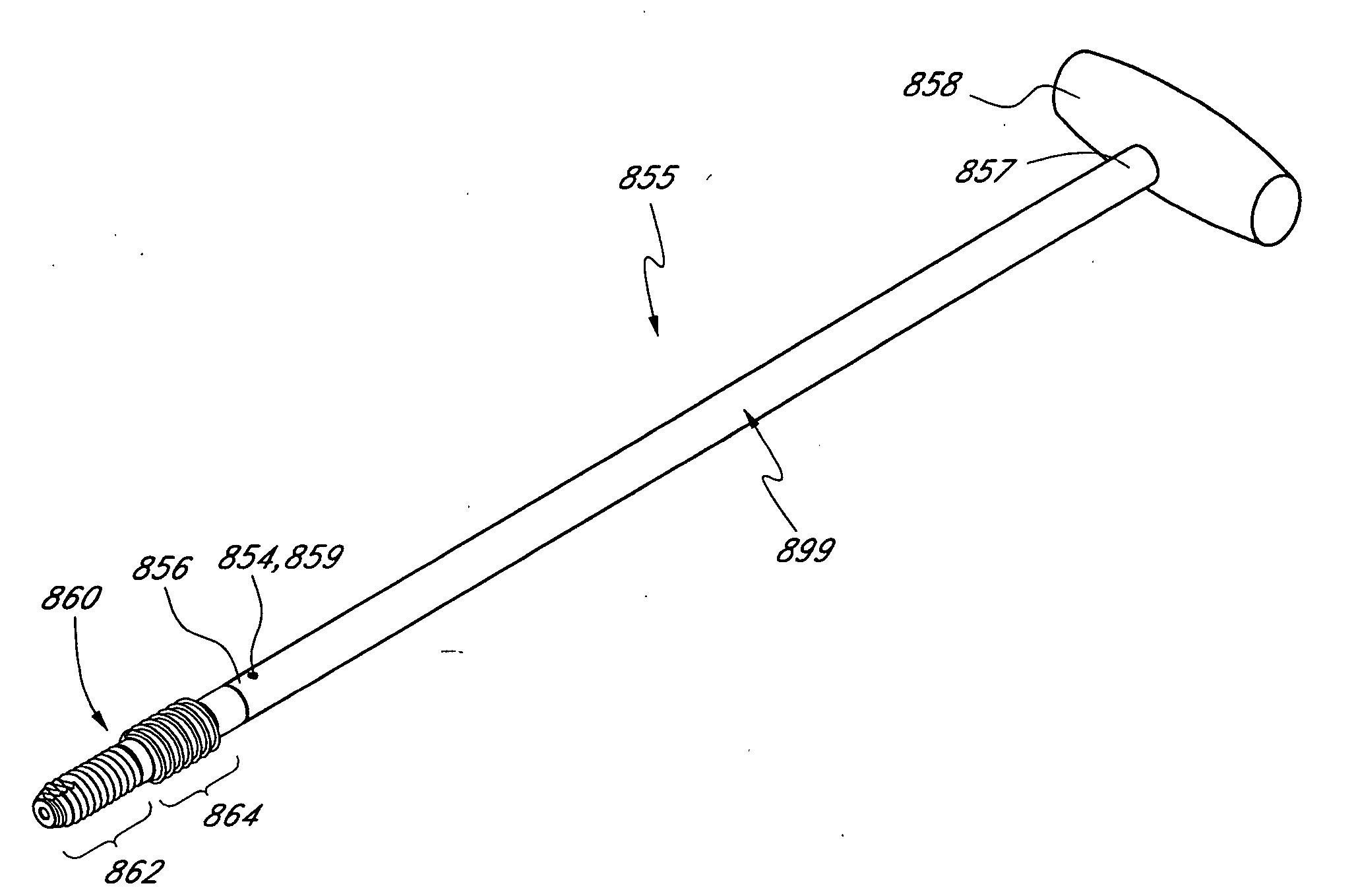
[0135] In accordance with one aspect of the embodiments described herein, there are provided surgical instrumentation systems and techniques for efficiently and atraumatically accessing and preparing treatment sites within the spine, such as, for example, vertebral motion segments, for subsequent therapeutic spinal procedures. In one approach, the step of accessing the treatment site includes using fluoroscopic imaging to visually align one or more components of the instrumentation system via a percutaneous, anterior trans-sacral axial approach. In another aspect, the treatment site includes a spinal disc and the subsequent therapeutic procedure includes nucleectomy. In yet another aspect, the therapeutic procedure includes immobilization devices to facilitate fusion; deployment of augmentation media; deployment of dynamic stabilization implants, or mobility devices to preserve or restore physiologic function.

[0136] In accordance with one aspect of the embodiments described herein,...


PUM

PropertyMeasurementUnit
diameteraaaaaaaaaa
lengthaaaaaaaaaa
axial lengthaaaaaaaaaa

Abstract

Disclosed are surgical tools, tool sets and methods for percutaneously accessing and preparing treatment sites within the spine for subsequent treatment procedures. The treatment site may be an inter-vertebral motion segments in the lumbar and sacral regions of the spine. The tool set may comprise introducer tools and bone dilators for accessing and tapping into a targeted site, such as, for example, the anterior surface of the S1 vertebral body. The tool set may also comprise cutters and extractors for preparing the treatment site for subsequent treatment procedures. The tool set may additionally comprise a bone graft inserter, an exchange system, and / or a temporary distraction tool for further preparing the treatment site for subsequent treatment procedures.

Description

RELATED APPLICATIONS [0001] This U.S. patent application claims priority and benefits from U.S. Provisional Patent Application No. 60 / 513,899, filed on Oct. 23, 2003, and co-pending U.S. patent application Ser. No. 10 / 309,416, filed on Dec. 3, 2002, which is a continuation-in-part of U.S. patent application Ser. No. 10 / 125,771, filed on Apr. 18, 2002, which is a continuation-in-part of U.S. patent application Ser. No. 09 / 848,556, filed on May 3, 2001, which is a continuation-in-part of U.S. patent application Ser. No. 09 / 782,583, filed on Feb. 13, 2001, which claims priority to U.S. Provisional Patent Application No. 60 / 182,748, filed on Feb. 16, 2000. This U.S. patent application also claims priority and benefits from co-pending U.S. patent application Ser. No. 10 / 853,476, filed May 25, 2004, which is a continuation of U.S. patent application Ser. No. 09 / 710,369, filed on Nov. 10, 2000. This U.S. patent application also claims priority and benefits from co-pending U.S. patent appli...

Claims


Application Information

Patent Timeline
Patent Type & Authority Applications(United States)
IPC IPC(8): A61B17/00A61B17/02A61B17/16A61B17/17A61B17/22A61B17/56A61B17/58A61B17/88A61B17/92A61L
CPCA61B17/0218A61B17/7074A61B17/1604A61B17/1615A61B17/1671A61B17/1697A61B17/1757A61B17/8615A61B17/888A61B17/8888A61B17/8897A61B2017/00261A61B2017/0046A61B2017/00469A61B2017/0256A61B2017/22038A61B2017/22044A61B2017/3445A61B2017/922A61B17/025A61B17/88A61B17/92A61B17/22
Inventor ASSELL, ROBERT L.AINSWORTH, STEPHEN D.CRAGG, ANDREW H.DICKHUDT, EUGENE A.
Owner MIS IP HLDG LLC
Why Eureka
Try Eureka