
KVM switch cable

a kvm switch and cable technology, applied in the direction of electrical apparatus casing/cabinet/drawer, coupling device connection, instruments, etc., can solve the problems of high operation cost of control of every computer with a set of these peripheral devices, high operating cost, and affecting the life of the kvm switch with the ps/2 interface, so as to facilitate the control of a computer, extend the life of the kvm switch, and control more conveniently

Active Publication Date: 2005-06-23
ATEN INT CO
View PDF7 Cites 31 Cited by
  • Summary
  • Abstract
  • Description
  • Claims
  • Application Information

AI Technical Summary

Benefits of technology

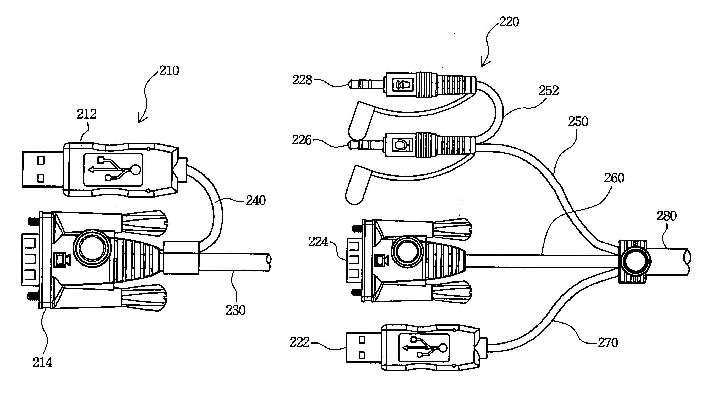
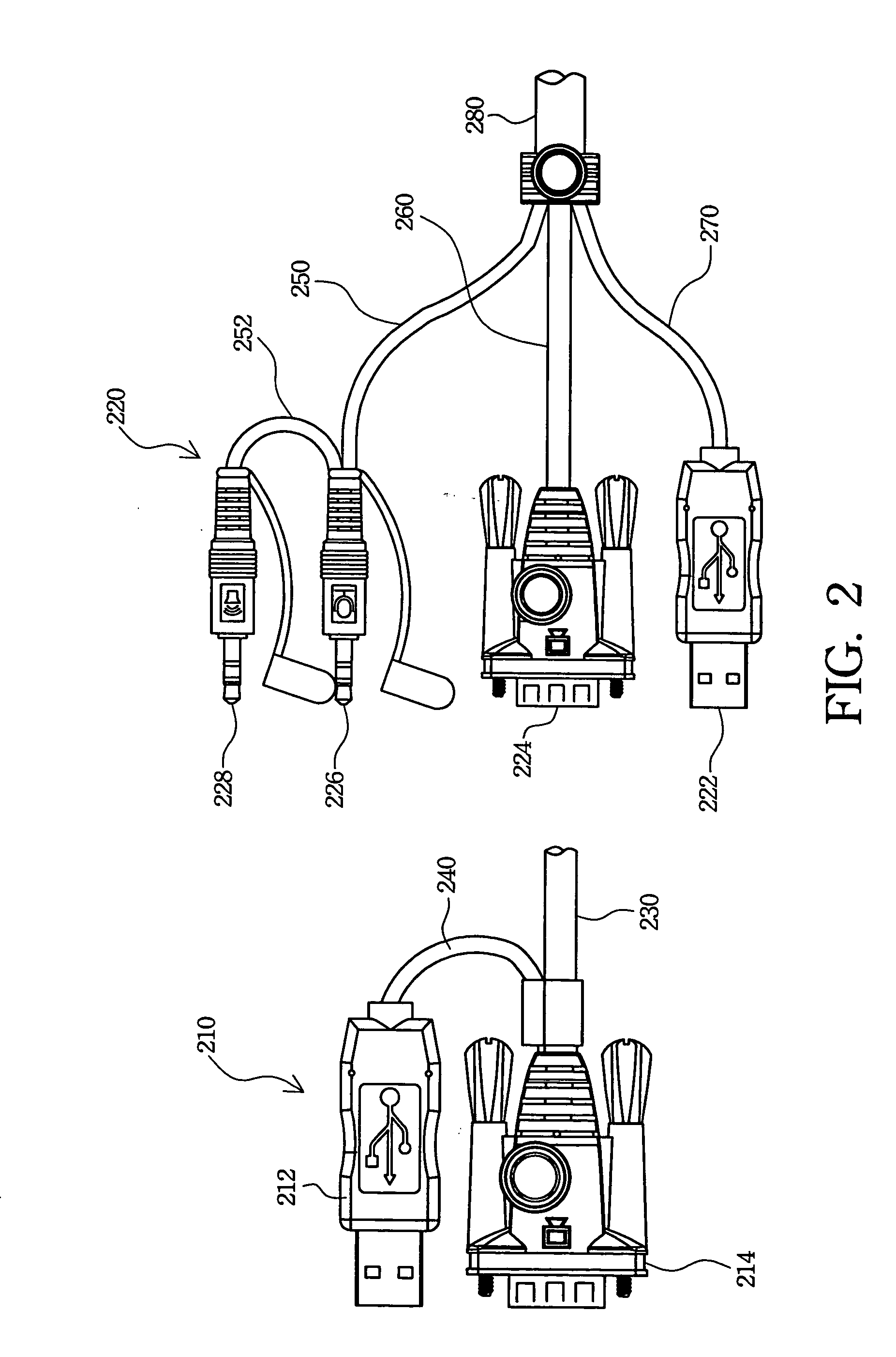
The present invention provides a KVM switch cable that allows a KVM switch to control a computer via the USB interface of the computer, even if the KVM switch does not have USB interfaces. The cable has a set of computer connectors, a cable, and a combination connector that can convert USB signals into PS / 2 signals and vice versa. This allows the KVM switch to control the computer using the USB interface, even if the KVM switch does not have USB interfaces. The cable also has connectors for audio signals and video signals, and can be used with a standard VGA HDB 15 connector or a special high density D sub 15 connector. The use of one cable to transmit signals between the computer and the KVM switch, and the conversion of USB into PS / 2 signals, extends the life-span of the KVM switch and reduces the hardware cost for computer upgrade.

Problems solved by technology

Control of every computer with a set of these peripheral devices incurs high operation costs and is not necessary.
Such peripheral devices also waste space.
However, due to development in electrical technology, computer products progress and change with each passing day.
Some computers, such as computers made by Sun or Apple, may not support PS / 2 interface.
Accordingly, the hardware cost for controlling the server computers and the control complexity are both increased.
Such a server computer management method not only increases the control complexity but also requires that the conventional computers be phased out sooner.
Therefore, the facility investment is increased, convenient server computer control is lost, and the management cost is also increased when the old computer is replaced with the new generation computer.

Method used


Image

  • KVM switch cable
  • KVM switch cable
  • KVM switch cable

Examples


Embodiment Construction

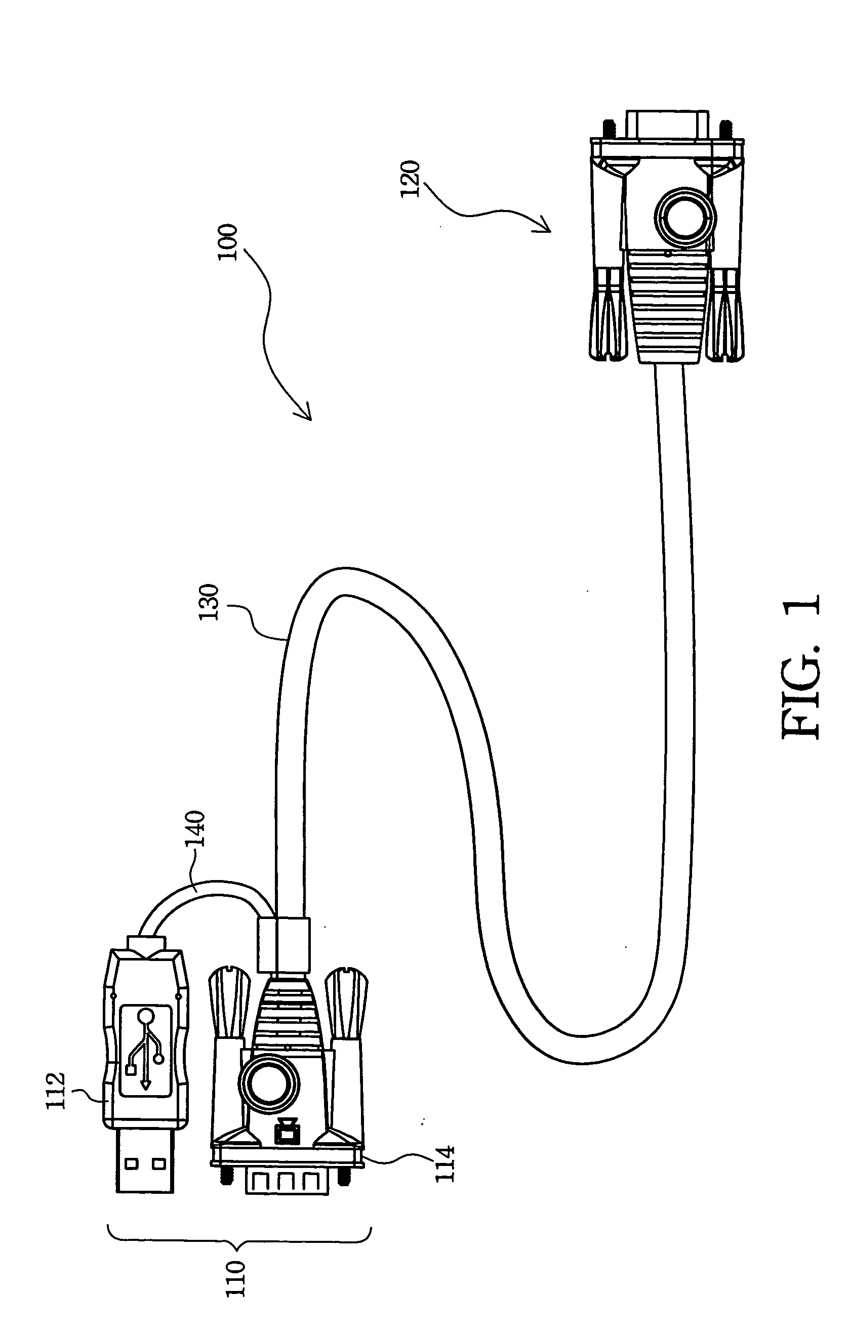
[0016]FIG. 1 is a schematic diagram of a KVM switch cable according to the present invention. The KVM switch cable 100 has a set of computer connectors 110, a combination connector 120, and a first transmitting cable 130. The set of computer connectors 110 is utilized to couple to input / output interfaces of a mouse, a keyboard, and a monitor of a computer, receive signals from the computer, and transmit signals to the combination connector 120 via the first transmitting cable 130. The combination connector 120 is coupled to an interface of a KVM switch, and transmits the signals from the first transmitting cable 130 to the KVM switch. The KVM switch also utilizes the first transmitting cable 130 to transmit commands ordered by a server computer administrator, from the combination connector 120 to the set of computer connectors 110, and to control the computer connected with the set of computer connectors 110.

[0017] A conventional KVM switch without USB interfaces is gradually phase...


PUM


Abstract

A KVM switch cable is described. The KVM switch cable transmits and converts signals between a USB interface and a PS / 2 interface for a computer and a KVM switch. Therefore, the life-span and application scope of the KVM switch with PS / 2 interfaces can be efficiently extended. The KVM switch cable has a set of computer connectors, a transmitting cable, and a combination connector, and further has a signal converting device installed in the set of computer connectors or the combination connector. The transmitting cable can transmit video signals of the computer to the KVM switch, mouse and keyboard signals to the computer, and can further simultaneously transmit microphone signals and speaker signals for the computer and the KVM switch.

Description

FIELD OF THE INVENTION [0001] The present invention relates to a KVM switch cable, and especially, to a KVM switch cable for transmitting keyboard, mouse, and video signals and exchanging PS / 2 signals and USB signals. BACKGROUND OF THE INVENTION [0002] The wide proliferation of personal computers and networks allows people to utilize the networks to search for and provide information. Currently, network requests are higher, and network-related enterprises have to buy large numbers of computers and network equipments to satisfy user requests. For example, Internet service providers and virtual host providers need to buy a lot of server computers to rent to users. Because these providers may supply a fast network environment, a lot of companies are willing to rent their server computers. The management and trouble shooting of these computers may become an important link. A larger server computer provider has thousands of server computers. Control of each of these computers requires a ...

Claims


Application Information

Patent Timeline
Patent Type & Authority Applications(United States)
IPC IPC(8): G06F13/12H01R31/00H01R31/06
CPCH01R31/005H01R2201/06H01R31/06
Inventor CHEN, SUN-CHUNG
Owner ATEN INT CO
Learn More