Massage brush

a brush and brush body technology, applied in the field of brushes, can solve the problems of inability to substitute, /i>will become useless, and the materials of pmma are usually more expensive than other polymers, and achieve the effect of convenient assembly and removal

Inactive Publication Date: 2005-06-30
HUANG CHU CHAU
View PDF3 Cites 21 Cited by
  • Summary
  • Abstract
  • Description
  • Claims
  • Application Information

AI Technical Summary

Benefits of technology

[0010] The primary object of the invention is therefore to specify a tightly engaged massage brush to prevent a massage structure thereof from being removed therefrom. The secondary object of the invention is therefore to specify an easily assembled and detached massage brush, the elements of which can be changed.
[0011] The third object of the invention is therefore to specify a massage brush that can be made of other polymer materials to reduce costs.
[0012] The fourth object of the invention is therefore to specify a massage brush that omits the back paste, so that design and material match problems need not be considered, and the manufacturing efficiency thereof is improved.
[0013] The fifth object of the invention is therefore to specify a massage brush with an appearance improved by omitting the back paste, thereby increasing the attractiveness thereof to purchasers.
[0014] According to the invention, this object is achieved by a massage brush including a massage structure, an orientation ring engaging tightly with the massage structure, a circular pad received in the massage structure, and an exterior cover retained against the circular pad and the orientation ring. The circular pad includes a flange disposed therearround and clamped in the massage structure, and an L-shaped restriction portion extending downwardly from a bottom thereof to support the orientation ring thereon. The orientation ring engages with the massage structure, the L-shaped restriction portion, and the exterior cover simultaneously for tightly clamping the massage structure therewith.

Problems solved by technology

However, the U-shaped fastening portion 111a of the conventional massage brush 1a becomes fatigued after long-term use and there is no retaining device or structure securing the U-shaped fastening portion 111a, so the U-shaped fastening portion 111a will be removed easily and the conventional massage brush 1a will become useless.
The PMMA materials are usually more expensive than other polymers, such as PP (polypropylene), PVC (polyvinyl chloride), and the like.
But these other materials cannot be substituted for the PMMA because of the back paste 14a and match problems there between, and that keeps the cost high.
In addition, the back paste 14a filled therein may be improper and overfilled, and the PMMA is a transparent material, so that the overfilled back paste 14a will be seen and negatively affect its attractiveness to purchasers.

Method used


Image

  • Massage brush
  • Massage brush
  • Massage brush

Examples


first embodiment

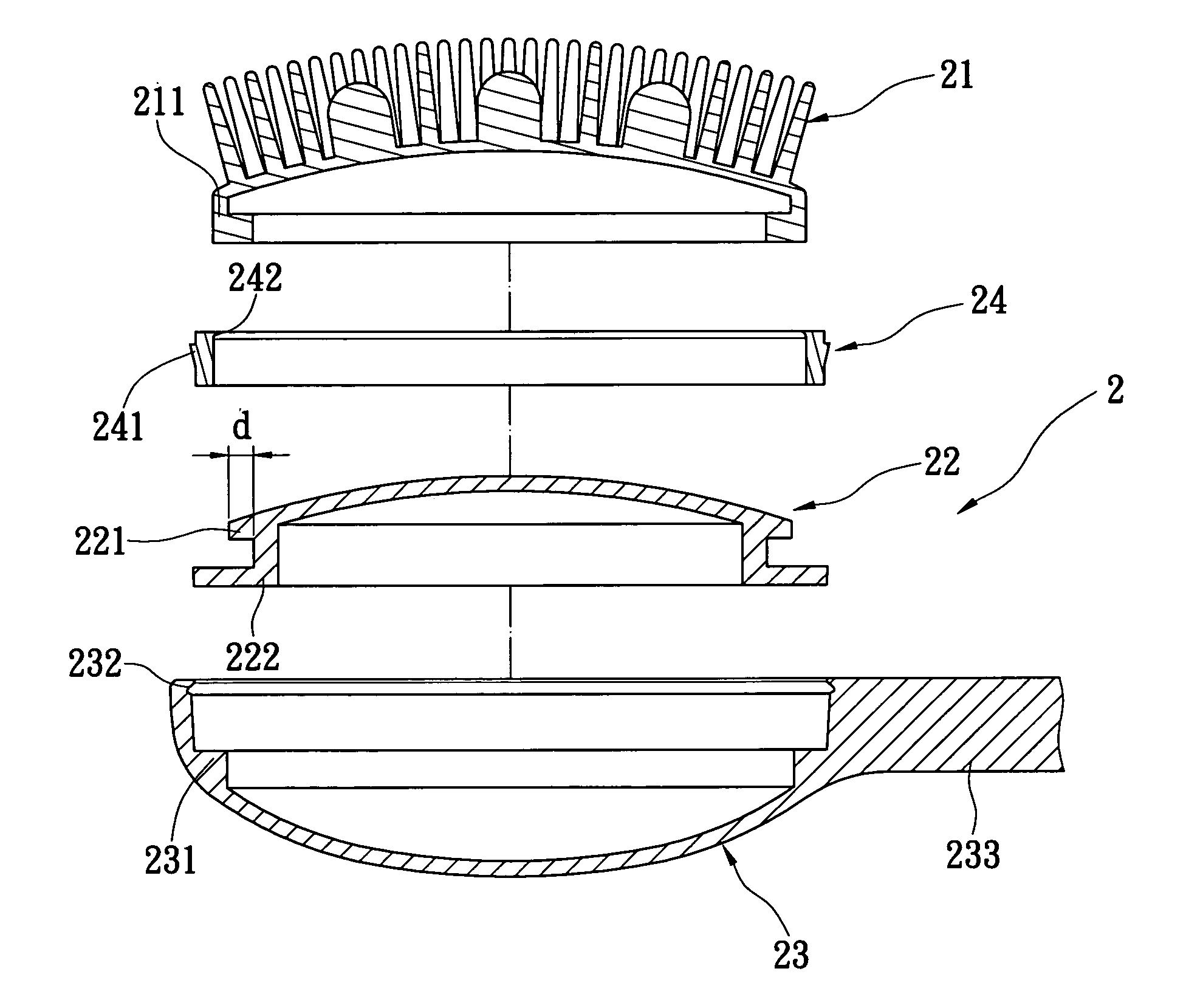
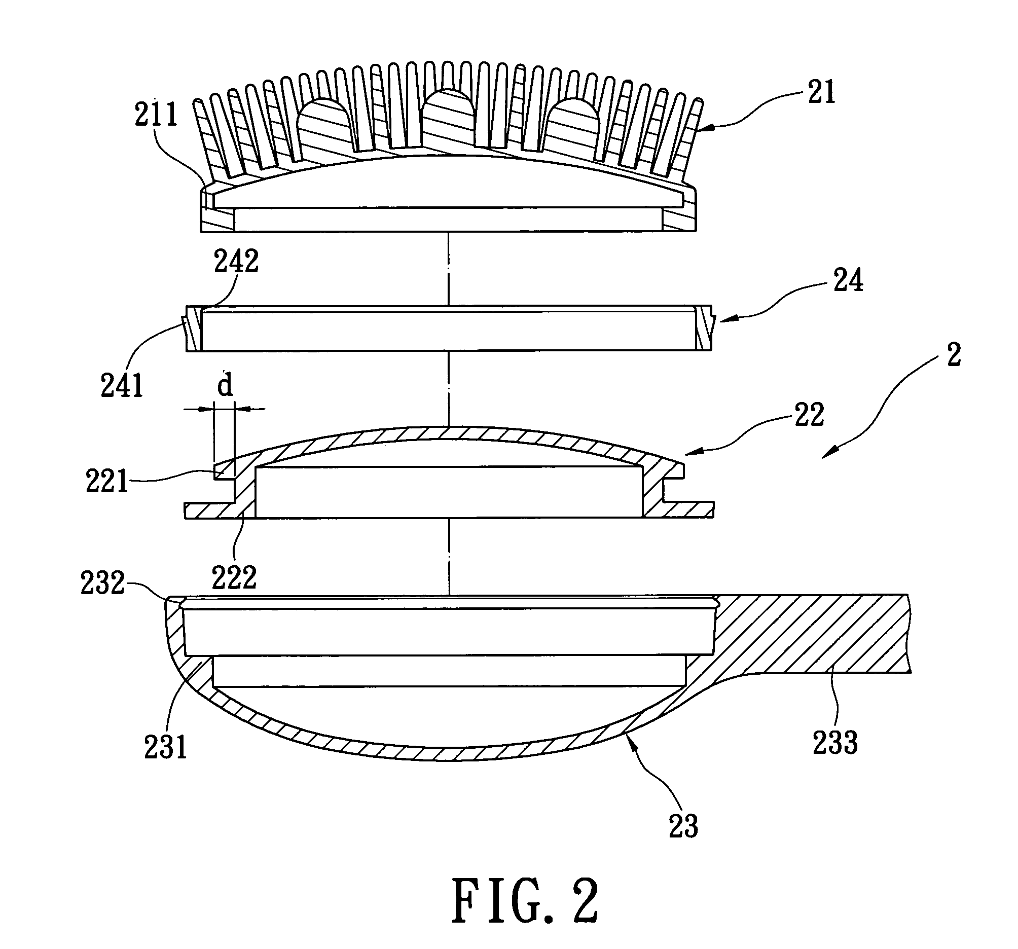
[0023] With respect to FIG. 2 and FIG. 4, a massage brush 2 according to the present invention is described. The massage brush 2 includes a massage structure 21, an orientation ring 24 engaged tightly with the massage structure 21, a circular pad 22 received in the massage structure 21, and an exterior cover 23 retained against the circular pad 22 and the orientation ring 24. The massage structure 21 has a U-shaped fastening portion 211 arranged circularly inwards and made integrally in one piece. The circular pad 22 includes a flange 221 disposed therearround and an L-shaped restriction portion 222 extends downwardly from a bottom of the circular pad 22, the flange 221 clamps in the U-shaped fastening portion 211 of the massage structure 21, the L-shaped restriction portion 222 is formed by drawing back a predetermined distance “d” from the flange 221 to receive the U-shaped fastening portion 211 and support the orientation ring 24 thereon. The exterior cover 23 further includes a ...

second embodiment

[0028] Referring to FIGS. 2 and 4, the exterior cover 23 includes a long handle 233 for manipulating. With respect to FIG. 5, the massage brush 2, the exterior cover 23 includes a pinch portion 234 extended from a top thereof. The pinch portion 234 has a curve body 2341 shaped ergonomically and a head 2342 connecting the curve body 2341, whereby the head 2342 is bigger than the curve body 2341. A user holds the curve body 2341 with the fingers and retains the head 2342 by the back of the hands.

third embodiment

[0029] In FIG. 6, in the massage brush 2, the pinch portion 234 is disposed on an end of the top of the exterior cover 23, and the head 2342 has a retention member 2343 extending forward from an opposite end thereof. The user clamps the curve body 2341 with the fingers and retains the head 2342 and the retention member 2343 by back of the hands.

[0030] The massage brush 2 includes the massage structure 21, the orientation ring 24 engaged tightly with the massage structure 21, the circular pad 22 received in the massage structure 21, and the exterior cover 23 retained against the circular pad 22 and the orientation ring 24. The flange 221 and the L-shaped restriction portion 222 of the circular pad 22 together provide the vertical clamping force in the upper-to-lower direction, and the flange 221 of the circular pad 22 and the orientation ring 24 together provide the horizontal clamping force in the right-to-left direction, for preventing the massage structure 21 from being removed th...


PUM


Abstract

A massage brush has a massage structure, an orientation ring engaging tightly with the massage structure, a circular pad received in the massage structure, and an exterior cover retained against the circular pad and the orientation ring. The circular pad includes a flange disposed therearround and clamps in the massage structure, and an L-shaped restriction portion extends downwardly from a bottom thereof to support the orientation ring thereon. The orientation ring engages with the massage structure, the L-shaped restriction portion, and the exterior cover simultaneously for tightly clamping the massage structure therewith.

Description

BACKGROUND OF THE INVENTION [0001] 1. Field of the Invention [0002] The present invention relates to a massage brush, and particularly relates to a massage brush with a tightly engaged massage structure to prevent the massage structure from being removed from the massage brush. [0003] 2. Background of the Invention [0004] Referring to FIG. 1, a conventional massage brush 1a includes a massage structure 11a, a circle pad 12a engaged with the massage structure 11a and an exterior cover 13a clamping the pad ring 12a. The massage structure 11a has a U-shaped fastening portion 111a made integrally in one piece and clipping a flange portion 121a of the circle pad 12a for the circle pad 12a to be received therein. The circle pad 12a has a circular recess 122a formed in a bottom thereof, and the exterior cover 13a has a circular protrusion 131a arranged integrally in one piece thereon and relating to the circular recess 122a for the circular protrusion 131a engaging in the circular recess 1...

Claims


Application Information

Patent Timeline
Patent Type & Authority Applications(United States)
IPC IPC(8): A46B1/00A46B3/22A46B5/00A46B5/02
CPCA46B3/22A46B5/0025A46B2200/102A46B5/0095A46B5/02A46B5/0062
Inventor HUANG, CHU CHAU
Owner HUANG CHU CHAU
Why Eureka
Try Eureka