Dry-wet thermal management system

a technology of thermal management system and spray cooling system, which is applied in the direction of lighting and heating apparatus, electrical apparatus casing/cabinet/drawer, domestic cooling apparatus, etc., can solve the problems of increasing the weight of the thermal management unit, the relatively high cost of creating a spray cooling system capable of thermal management all, and the inability to efficiently cool modern high-end electronics. , to achieve the effect of reducing the cost of electronic devices, reducing weight and size, and cost-effective and efficien

Inactive Publication Date: 2005-06-30
PARKER INTANGIBLES LLC
View PDF32 Cites 20 Cited by
  • Summary
  • Abstract
  • Description
  • Claims
  • Application Information

AI Technical Summary

Benefits of technology

[0019] Another object is to provide a dry-wet thermal management system that is cost effective and efficient.
[0020] An additional object is to provide a dry-wet thermal management system that has a reduce weight and size.
[0021] A further object is to provide a dry-wet thermal management system that reduces the cost of electronic devices utilized by reducing the need for coolant tolerant specifications.
[0022] Another object is to provide a dry-wet thermal management system that reduces coolant loss within a spray cooling system by reducing access to the spray chamber.
[0023] A further object is to provide a dry-wet thermal management system that effectively cools low heat flux and high heat flux electronic components.
[0025] An additional object is to provide a dry-wet thermal management system that increases system reliability and access.

Problems solved by technology

Conventional dry cooling technology simply is not capable of efficiently cooling modern high-end electronics.
While there are many benefits in utilizing spray cooling technology, there are some detriments.
One of the detriments with spray cooling technology is the relatively high cost of creating a spray cooling system capable of thermally managing all of the electronic devices, electronic cards and the like for an electronic system.
Another problem with spray cooling technology is the increased weight of the thermal management unit.
A further problem with spray cooling technology is that not all electronic devices are suitable for usage within a liquid coolant environment.
Another problem with spray cooling technology is that to replace, repair or test any electronic device within a spray chassis the seal must be broken to the spray chassis thereby leading to the loss of coolant.
While these devices may be suitable for the particular purpose to which they address, they are not as suitable for providing simultaneous spray cooling and dry cooling for a plurality of cards sharing a common backplane.

Method used


Image

  • Dry-wet thermal management system
  • Dry-wet thermal management system
  • Dry-wet thermal management system

Examples


Embodiment Construction

A. Overview

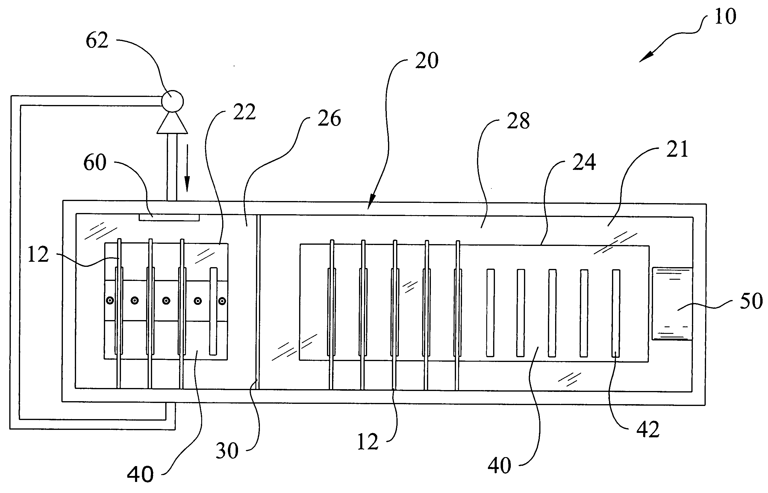
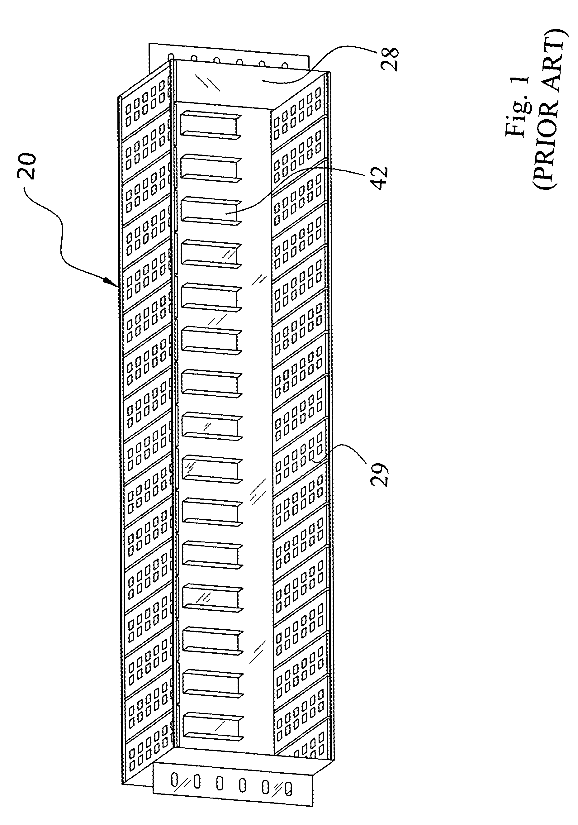
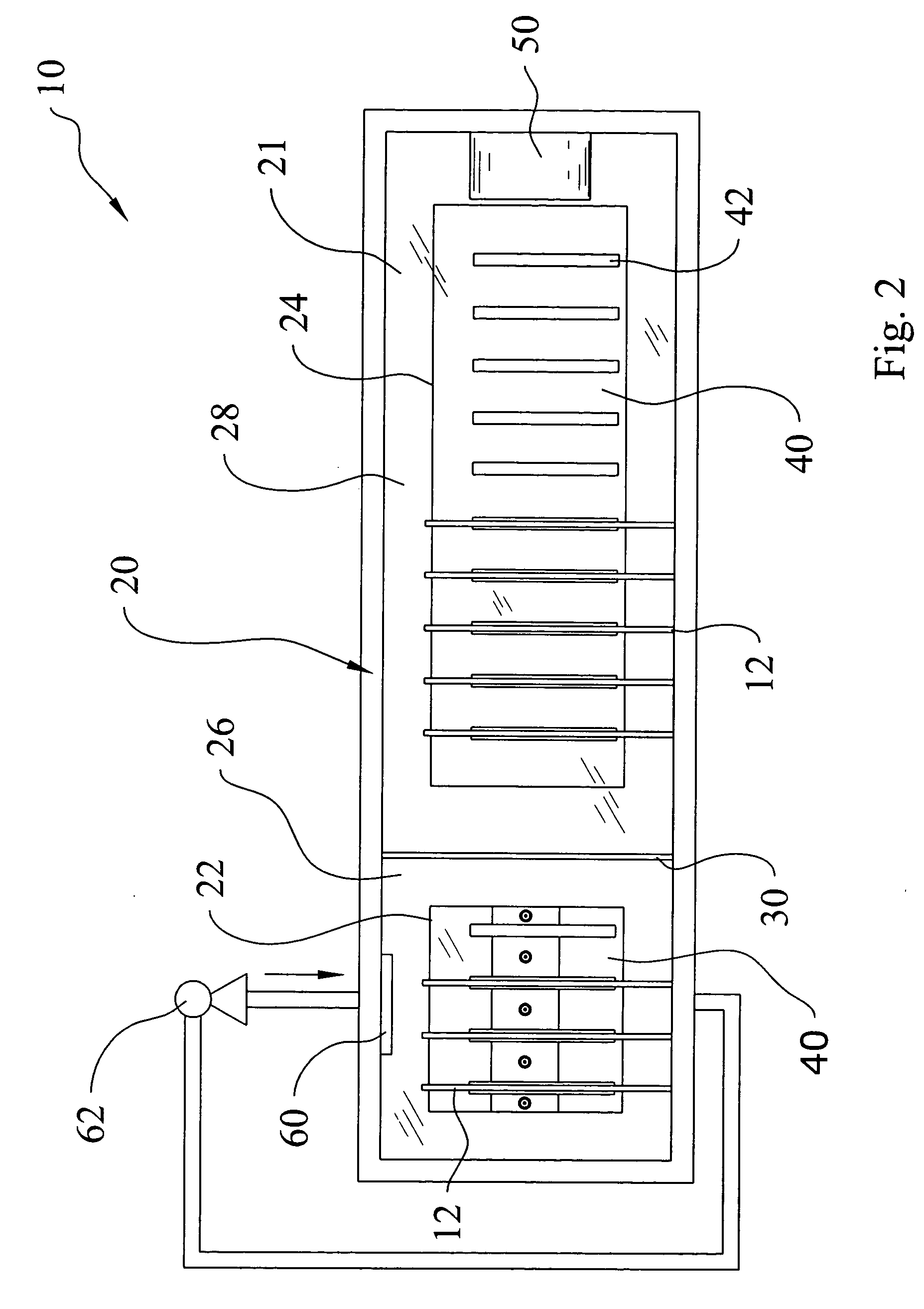
[0038] Turning now descriptively to the drawings, in which similar reference characters denote similar elements throughout the several views, FIGS. 2 through 9 illustrate a dry-wet thermal management system 10, which comprises a chassis 20 having a dry chamber 28 and a spray chamber 26, a first opening 22 within a rear portion 21 of the chassis 20 extending into the spray chamber 26, a second opening 24 within the rear portion 21 of the chassis 20 extending into the dry chamber 28, and a main backplane 40 secured and sealed to the rear portion 21 of the chassis 20. Electronic cards 12 may be electrically coupled within sockets 42 of the main backplane 40 within both the dry chamber 28 and the spray chamber 26. The cards 12 within the spray chamber 26 are typically high heat flux components with increased cooling requirements and the cards 12 within the dry chamber 28 are typically low heat flux components with reduced cooling requirements and / or are not compatible with th...


PUM


Abstract

A dry-wet thermal management system for providing simultaneous spray cooling and dry cooling for a plurality of cards. The dry-wet thermal management system includes a chassis having a dry chamber and a spray chamber, a first opening within a rear portion of the chassis extending into the spray chamber, a second opening within the rear portion of the chassis extending into the dry chamber, and a main backplane secured and sealed to the rear portion of the chassis. Electronic cards may be electrically coupled within sockets of the main backplane within both the dry chamber and the spray chamber. The cards within the spray chamber are typically high heat flux components with increased cooling requirements and the cards within the dry chamber are typically low heat flux components with reduced cooling requirements. A spray cool system is within the spray chamber and a dry cool system is within the dry chamber.

Description

CROSS REFERENCE TO RELATED APPLICATIONS [0001] Not applicable to this application. STATEMENT REGARDING FEDERALLY SPONSORED RESEARCH OR DEVELOPMENT [0002] Not applicable to this application. BACKGROUND OF THE INVENTION [0003] 1. Field of the Invention [0004] The present invention relates generally to spray cool thermal management devices and more specifically it relates to a dry-wet thermal management system for providing simultaneous spray cooling and dry cooling for a plurality of electronic cards. [0005] 2. Description of the Related Art [0006] The present invention relates to the thermal management of electronic components that are mounted upon electronic cards (a.k.a. expansion boards) or substrates. In a card level system, a plurality of cards are electrically connected within sockets upon a backplane (e.g. motherboard, etc.). Electronic cards are utilized in various applications such as personal computers, workstations, server computers, rack mounted services, network routers,...

Claims


Application Information

Patent Timeline
Patent Type & Authority Applications(United States)
IPC IPC(8): F25D17/06F26B19/00F26B25/06H05K7/14H05K7/20
CPCH05K7/1425H05K7/20672H05K7/20345
Inventor KNIGHT, PAUL A.KABRELL, CARL AXEL INGEMAR
Owner PARKER INTANGIBLES LLC
Why Eureka
Try Eureka