Photovoltaic systems and methods

a photovoltaic system and photovoltaic technology, applied in photovoltaic energy generation, photovoltaics, electrical equipment, etc., can solve the problems of high manufacturing cost and low manufacturing yield, unfilled trenches in the lower region, and inconvenient operation

Inactive Publication Date: 2005-06-30
SHIM YOUNGTACK
View PDF0 Cites 44 Cited by
  • Summary
  • Abstract
  • Description
  • Claims
  • Application Information

AI Technical Summary

Benefits of technology

[0045] The term “lateral direction” generally means a direction along a horizontal and long axis of the photovoltaic system, whereas the term “vertical direction” usually refers to a direction along a vertical and short axis of the photovoltaic system.
[0046] The term “conductive” generally means a property of a material allowing passage of electrons and / or holes therethrough. A “conductive material” is a material with a r sistivity less than 10−2 ohm-cm, and is generally inclusive of “semiconductive material” of which the resistivity is between 10−2 and 105 to 1010 ohm-cm, where the conductivity is defined as a resistance multiplied by a cross-sectional area divided by a length.
[0047] A material having an “n polarity,”“n conductivity type” or simply “n type” generally refers to a conductive material and, more particularly, a semiconductive material having at least one extra or free electron. A material having a “p polarity,”“p conductivity type” or simply “p type” generally refers to a conductive material and, more particularly, a semiconductive materials at least one hole (i.e., absence of an electron). An n or p type charge layer may be made of or include materials intrinsically having at least one extra electron or hole or may be made of or include materials doped by n or p type dopants.
[0048] A “charge layer” is a layer made of or include at least one material capable of attracting either an electron or hole theretoward. A “conductive contact layer” or “contact layer” is a layer made of or including at least one material having a resistivity less than that of the “charge layer” of n or p polarity and / or that of an inert layer which does not have either polarity and, therefore, is neutral. Both of the “charge layer” and “contact layer” may be provided by employing, e.g., conventional semiconductor fabrication processes including exemplary steps of, e.g., chemical or physical deposition of substrate layers, doping at least portions of such layers, masking of doped or undoped layers, etching at least portions of such layers, and so on. These layers may be provided by other conventional techniques such as, e.g., direct solution casting, indirect solution casting which requires heat treatment following casting, wafer bonding, and the like. It is appreciated that “charge layers” may be used to collectively refer to any or all “charge layers” of any member and having any polarity such as, e.g., the p polarity, n polarity, and neutral polarity. However, an upper, intermediate, and lower “charge layer” may refer respectively to an uppermost, intermediate, and lowermost “charge layer” of any or all members such as the first member, second member, third member, and so on.
[0049] As used herein, the terms “charge layer” and “planar layer” represent any layer which may be made of materials arranged to allow movements of electrons and / or holes thereacross. The “charge layer” is generally a layer made of such materials, while the “planar layer” refers to a layer which may be made of such materials and which are specifically made by conventional semiconductor fabrication processes. Accordingly, the “charge layer” is inclusive of the “planar layer” and to be interpreted as such unless otherwise specified.
[0050] The term “connection” is generally synonymous with “electrical connection” and / or “electrical contact.” Therefore, “connection,”“electrical connection,” and / or “electrical contact” generally refer to a macroscopic, planar, and / or microscopic structures which allow passage of electrons and / or holes therethrough, example of which may include, but not be limited to, physical contacts between two or more objects, deposition of a conductive contact layer between, over or below two objects, soldering two or more objects, and the like. Accordingly, when two members are connected, they may contact each other by a series and / or parallel connection. In particular, when such members are connected in series, voltages generated by each member are to be added to each other. When a proposition “to” is used with the terms “connection” and “contact,” it typically refers to a structure in which two or more layers, members, and / or objects are arranged to directly or indirectly touch each other.

Problems solved by technology

The conventional devices, however, have the drawback of high manufacture cost and low manufacturing yields.
As a result, the deposited or grown insulating material may pinch off and close an upper opening of the trench while leaving the lower region of the trench unfilled.
Such gaps in the trench weaken the insulating properties of the trench and can produce PV devices with lower voltage ratings and poor mechanical properties.
This problem is also exacerbated when the trench is etched with the upper part of the walls at a re-entrant angle which may produce a pinch-off region in which the upper opening of the trench is closed off while leaving the lower region in the trench unfilled.
Such interconnects are traditionally less than 0.05 mm thick, and are attached to the PV cells using an extremely time consuming manual soldering or welding process or, alternatively, using an elaborate and expensive automated process.
In addition to being highly labor intensive, welding or soldering the delicate interconnects to the PV cells is typically a high risk procedure which may result in frequent breakage of the expensive PV cells as well as a high rate of attrition.

Method used


Image

  • Photovoltaic systems and methods
  • Photovoltaic systems and methods
  • Photovoltaic systems and methods

Examples


Embodiment Construction

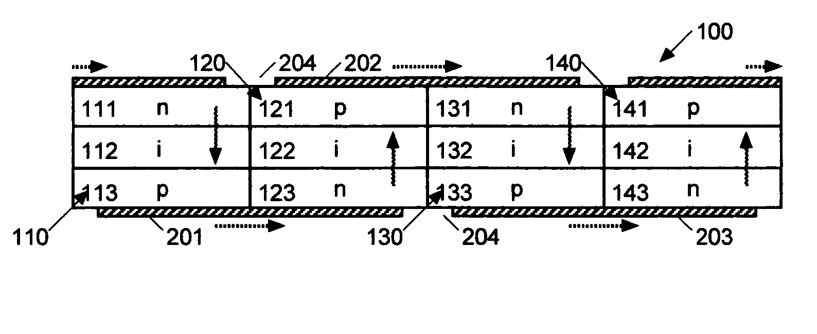
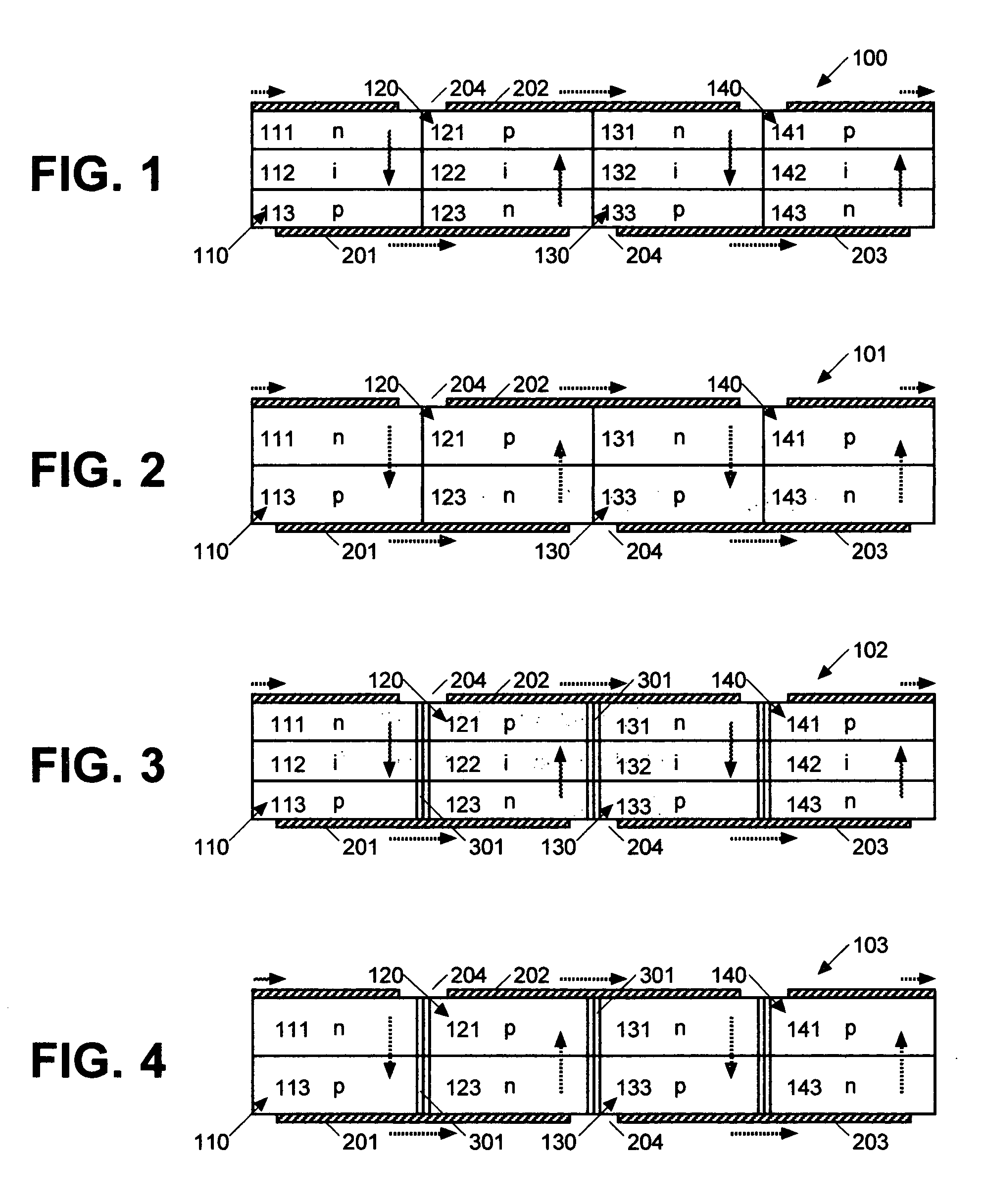
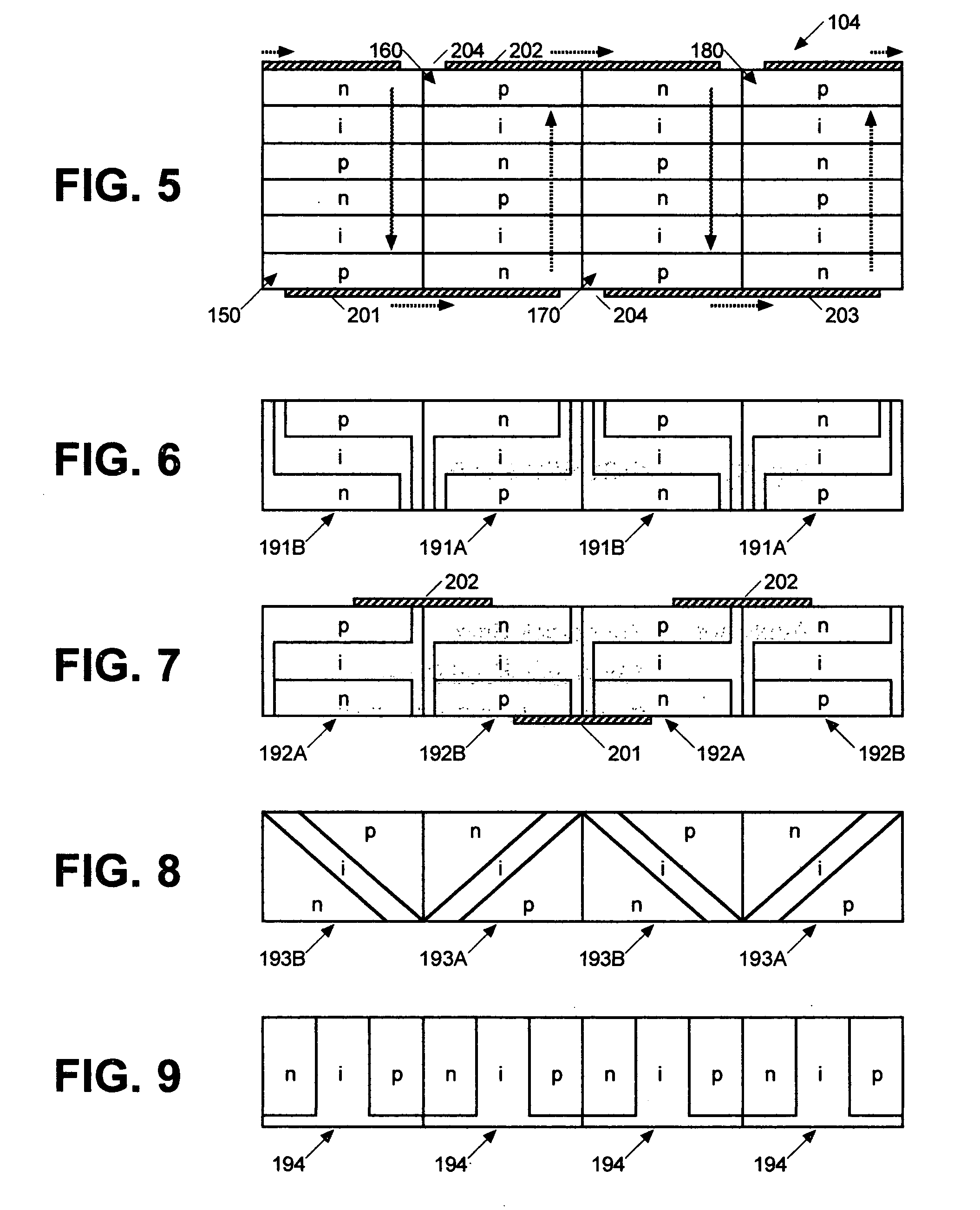
[0066] The present invention generally relates to various photovoltaic systems capable of generating electric energy in response to various electromagnetic waves projected thereupon and, optionally, at least partially transmitting such waves therethrough. More particularly, the present invention relates to planar arrangements and methods of such photovoltaic systems where photovoltaic members are electrically connected in series though top and / or bottom charge and / or planar layers thereof, through substantially horizontal contact layers connecting such top and / or bottom layer, and / or through other equivalent structures without using any conventional vertical interconnects which generally traverse multiple charge and / or planar layers vertically. As will be described herein, such series connections are obtained in such a photovoltaic system by arranging the charge and / or planar layers of adjacent members to have polarities alternating in reverse orders. In other words, the photovoltai...


PUM


Abstract

The present invention generally relates to various photovoltaic systems capable of generating electric energy in response to various electromagnetic waves projected thereupon and, optionally, at least partially transmitting such waves therethrough. More particularly, the present invention relates to planar arrangements and methods of such photovoltaic systems where photovoltaic members are electrically connected in series without employing any conventional vertical interconnects. Therefore, an exemplary photovoltaic system includes multiple photovoltaic members each of which is arranged to include multiple charge layers, where such members are arranged to be disposed laterally and side by side, where the charge layers of each of the members are arranged to be disposed vertically and contacting each other and to have different polarities arranged in a preset order in order to generate voltage in response to said waves, where at least two of the members are arranged to be disposed adjacent to each other, to generate the voltages in opposite vertical direction, and to be connected in series by their top and/or bottom charge layers in order to enable the system to generate the driving voltage greater than each of the voltages generated by such members. Such a present invention also relates to various methods of providing such photovoltaic system and/or members thereof. In addition, the present invention further relates to various process of providing such photovoltaic systems and/or members thereof.

Description

[0001] The present application claims a benefit of a Disclosure Document Number 503,103 which is entitled “Photovoltaic System” and filed on Jan. 3, 2002, an entire portion of which is incorporated herein by reference.FIELD OF THE INVENTION [0002] The present invention generally relates to various photovoltaic systems capable of generating electric energy in response to various electromagnetic waves projected thereupon and, optionally, at least partially transmitting such waves therethrough. More particularly, the present invention relates to planar arrangements and methods of such photovoltaic systems where photovoltaic members are electrically connected in series without employing any conventional vertical interconnects. In addition, the present invention relates to various process of providing such photovoltaic systems. BACKGROUND OF THE INVENTION [0003] Various photovoltaic (will be abbreviated as “PV” hereinafter) devices of many different types have been in use so as to conver...

Claims


Application Information

Patent Timeline
Patent Type & Authority Applications(United States)
IPC IPC(8): H01L31/00
CPCH01L31/03529H01L31/0504Y02E10/548H01L31/076H01L31/075
Inventor SHIM, YOUNGTACK
Owner SHIM YOUNGTACK
Why Eureka
Try Eureka