Organic electroluminescent device having supporting plate and method of fabricating the same

a technology of electroluminescent devices and supporting plates, which is applied in the direction of organic semiconductor devices, discharge tubes luminescnet screens, printed circuit non-printed electric components association, etc., can solve the problems of affecting the brightness of passive matrix organic eld, requiring a relatively large amount of power to operate, and it is substantially difficult to achieve high brightness in the transmissive region of this bottom emission type, so as to prevent overheating

Active Publication Date: 2005-06-30
LG DISPLAY CO LTD
View PDF12 Cites 22 Cited by
  • Summary
  • Abstract
  • Description
  • Claims
  • Application Information

AI Technical Summary

Benefits of technology

[0016] An object of the present invention is to provide an organic EL d

Problems solved by technology

While both the passive matrix organic ELD and the active matrix organic ELD have a simple structure and are formed by a simple fabricating process, the passive matrix organic ELD requires a relatively large amount of power to operate.
In addition, the display size of a passive matrix organic ELD is limited by the width and thickness of conductive lines used in the structure.
However, it is substantially difficult to obtain high brightness in a trans

Method used


Image

  • Organic electroluminescent device having supporting plate and method of fabricating the same
  • Organic electroluminescent device having supporting plate and method of fabricating the same
  • Organic electroluminescent device having supporting plate and method of fabricating the same

Examples


Embodiment Construction

[0032] Reference will now be made in detail to the illustrated embodiments of the present invention, examples of which are illustrated in the accompanying drawings. An organic ELD can be a single panel type in which an array element layer and an organic EL diode are formed in a single panel, or a dual panel type in which the array element layer and the organic EL diode are formed on their own respective substrates. Wherever possible, the same reference numbers will be used throughout the drawings to refer to the same or like parts.

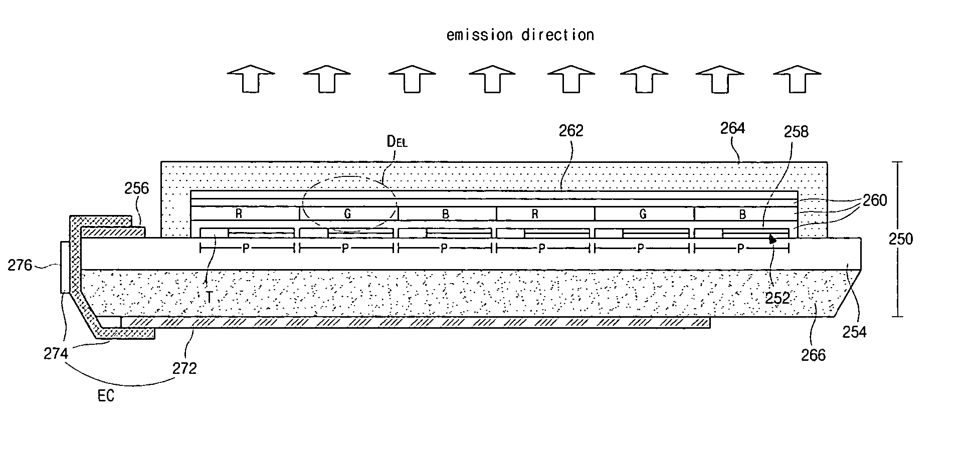
[0033]FIGS. 3A and 3B are cross-sectional views of a top emission type organic ELD according to an embodiment of the present invention. As shown in FIG. 3A, a top emission type organic ELD 250 includes an array element layer 252 on a substrate 254 including a pad 256, a first opaque electrode 258, an organic EL layer 260 on the first electrode 258, and a second substantially transparent electrode 262. The first electrode 258, the organic EL layer 260 and ...


PUM


Abstract

An organic electroluminescent device includes: an array element layer having a pad on a first substrate having first and second sides; an organic electroluminescent diode connected to the array element, the organic electroluminescent diode emitting light in an opposite direction away from the first substrate; a printed circuit board adjacent to a backside of the first substrate, the printed circuit board supplying the array element with external signals through the pad; and a supporting plate between the first substrate and the printed circuit board, the supporting plate having better thermal conductivity than the first substrate.

Description

[0001] The present invention claims the benefit of Korean Patent Application No. 2003-0099355 filed in Korea on Dec. 29, 2003, which is hereby incorporated by reference. BACKGROUND OF THE INVENTION [0002] 1. Field of the Invention [0003] The present invention relates to a display device, and more particularly, to an organic electroluminescent device and a method of fabricating the same. [0004] 2. Discussion of the Related Art [0005] In general, an organic electroluminescent device (ELD) emits light by injecting electrons from a cathode and holes from an anode into an emission layer, combining the electrons with the holes, generating an exciton, and transitioning the exciton from an excited state to a ground state. In comparison to a liquid crystal display (LCD) device, an additional light source is not necessary for the organic ELD to emit light because the transition of the exciton between the two states causes light to be emitted. Accordingly, the size and weight of the organic EL...

Claims


Application Information

Patent Timeline
IPC IPC(8): H01J1/62H05B33/00H01L27/32H01L51/52H05B33/10H05B33/12H05B33/26H05B44/00H05K1/18H05K7/20
CPCH01L27/3244H01L27/3251H01L2251/5315H01L51/529H01L27/3276H10K59/127H10K59/12H10K59/131H10K50/87H10K2102/3026H05B33/00
Inventor PARK, JAE-YONGLEE, NAM-YANG
Owner LG DISPLAY CO LTD
Why Eureka
Try Eureka