Transformer structure

a transformer and winding technology, applied in the direction of basic electric elements, coils, electrical apparatus, etc., can solve the problems of increasing the cost of transformers, so as to increase the leakage inductance, reduce the coupling coefficient, and improve the effect of electricity security

Active Publication Date: 2005-06-30
DELTA ELECTRONICS INC
View PDF5 Cites 19 Cited by
  • Summary
  • Abstract
  • Description
  • Claims
  • Application Information

AI Technical Summary

Benefits of technology

[0009] A first object of the present invention is to provide a transformer structure by separating the primary winding coil and the secondary winding coil thereof to decrease the coupling coefficient and increase the leakage inductance. The transformer structure according to the present invention is advantageous in terms of a uncomplicated circuit arrangement, and is capable of upgrading the electricity security, simplifying the manufacturing procedure, and saving the laboring effort and manufacturing cost.

Problems solved by technology

Although the transformer structure shown in FIG. 2 can increase the leakage inductance of transformer, there still exists numerous problems needing to be conquered.
Because the tape 24 is a soft material and is not possible to be thoroughly affixed, the transformer windings would bear a weak structure and would be susceptible to displacement after a long usage time.
This would lead to a lower or unstable leakage inductance, and would further affect the regulation on the resonant circuit of the power supply system.
Since the tape has viscosity and has a relatively small width, the laboring efforts expended on tape winding will be time-consuming and complicated.
This would limit the promotion of yield and cause wastes on manpower and cost.
Also, the quality of transformer would be seriously deteriorated due to the improper winding of the tapes.
What is worse, as the melting point of the tape is relatively low, the maximum operating temperature of transformer is unavoidably limited, resulting in a narrow applicability for the transformer.

Method used


Image

  • Transformer structure
  • Transformer structure
  • Transformer structure

Examples


Embodiment Construction

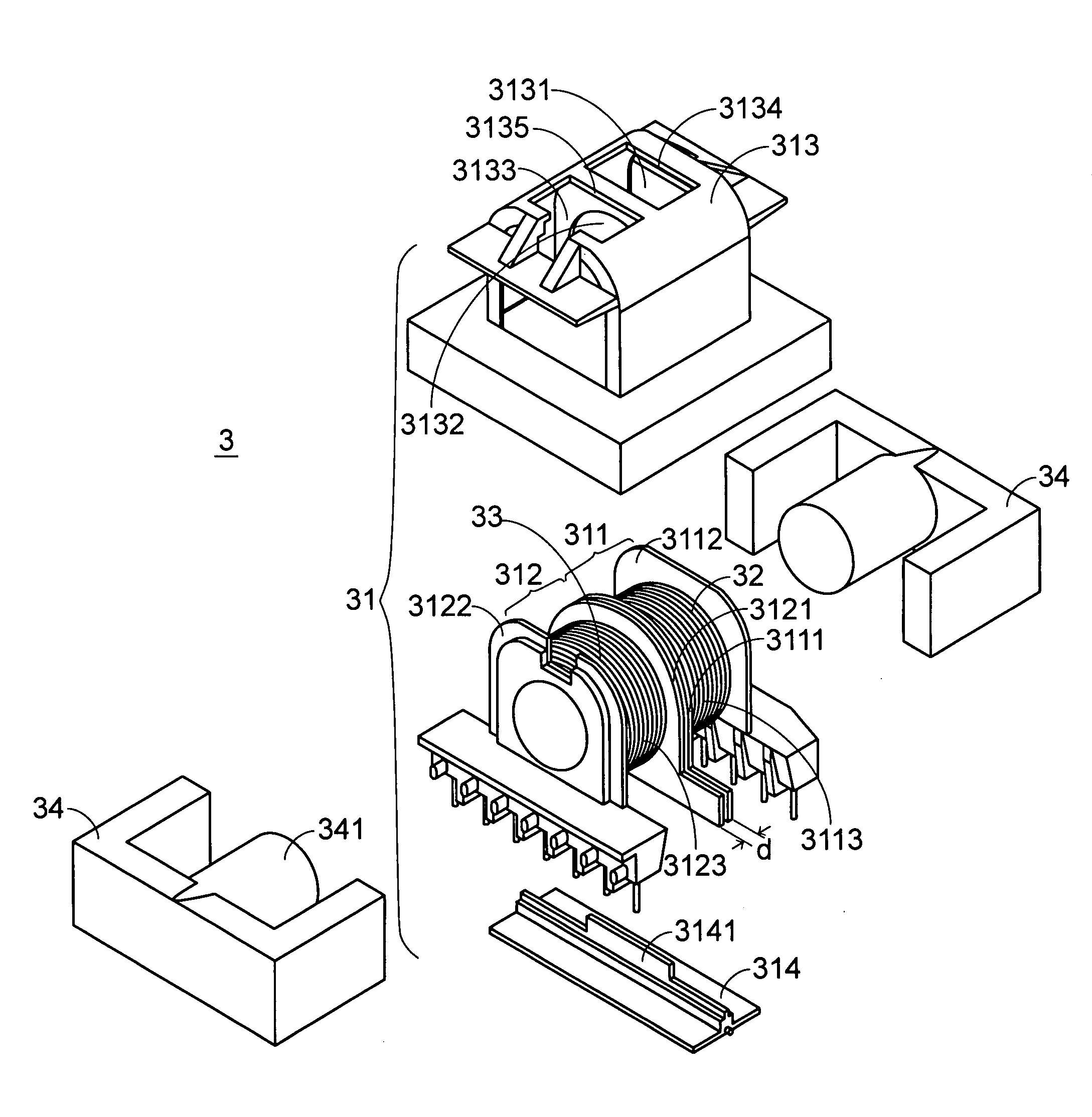
[0031] Referring to FIG. 3(a), which shows a transformer structure with a leakage inductance according to a preferred embodiment of the present invention. As shown in FIG. 3(a), the transformer according to the present invention is constituted by a bobbin module 31, a primary winding coil 32, a secondary winding coil 33, and a magnetic core assembly 34. The bobbin module 31 includes a first winding window portion 311, a second winding window portion 312, and a bobbin case 313. The primary winding coil 32 and the secondary winding coil 33 are wound around the first winding window portion 311 and the second winding window portion 312, respectively. The magnetic core assembly 34 can be shaped in the form of an EE-core, an El-core, or an ER-core, in which a central leg 341 thereof is mounted within the bobbin module 31 so that the magnetic core assembly 34 can achieve a magnetic coupling effect with the primary winding coil 32 and the secondary winding coil 33, and thereby perform volta...


PUM

PropertyMeasurementUnit
specific distanceaaaaaaaaaa
winding areaaaaaaaaaaa
leakage inductanceaaaaaaaaaa

Abstract

A transformer structure is proposed herein which includes a primary winding coil, a secondary winding coil, a bobbin module, and a magnetic core assembly. The magnetic core assembly is mounted within the bobbin module. The bobbin module includes a first winding window portion and a second winding window portion in which the first winding window portion allows the primary winding coil to be wound thereupon and the second winding window portion allows the secondary winding coil to be wound thereupon. Both of first winding window portion and the second winding window portion include a first lateral plate, and each couples or separate with each other by the first lateral plate, such that the primary winding coil and the secondary winding coil are separated with each other and the leakage inductance, and the safe distance of electrical security for the transformer is increased accordingly.

Description

FIELD OF THE INVENTION [0001] The present invention is related to a transformer structure, and more particularly to a transformer structure with an increased leakage inductance, an improved electrical security, a simpler construction, less manpower for assembling, and a reduced manufacturing cost. BACKGROUND OF THE INVENTION [0002] Transformer has been widely introduced into a variety of electric appliances as a basic circuit component. Referring to FIG. 1, which shows a typical representation of a conventional transformer structure. As shown in FIG. 1, a conventional transformer 1 includes a magnetic core assembly 11, a bobbin 12, a primary winding coil 13, and a secondary winding coil 14. The primary winding coil 13 and the secondary winding coil 14 are wound up and down in the winding area within the bobbin 12, and are separately isolated by a tape 15. The magnetic core assembly 11 is generally shaped in the form of an EE-core, an El-core, or an ER-core, wherein a central leg 111...

Claims


Application Information

Patent Timeline
Patent Type & Authority Applications(United States)
IPC IPC(8): H01F27/02H01F27/30H01F27/32
CPCH01F27/027H01F2005/043H01F27/325H01F27/306
Inventor CHANG, SHIH-HSIEN
Owner DELTA ELECTRONICS INC
Why Eureka
Try Eureka