
Video camera

a video camera and camera body technology, applied in the field of video cameras, can solve the problems of complicated appearance, unfavorable video camera color variation development, and inability to directly apply the video camera to the system of color variation development, etc., to achieve the effect of easy replacement and less visibl

Inactive Publication Date: 2005-06-30
HITACHI LTD
View PDF3 Cites 40 Cited by
  • Summary
  • Abstract
  • Description
  • Claims
  • Application Information

AI Technical Summary

Benefits of technology

[0011] The exterior decorative member preferably is configured to be easily replaced with another decorative member without using special tools to enable the user change the appearance of the video camera.
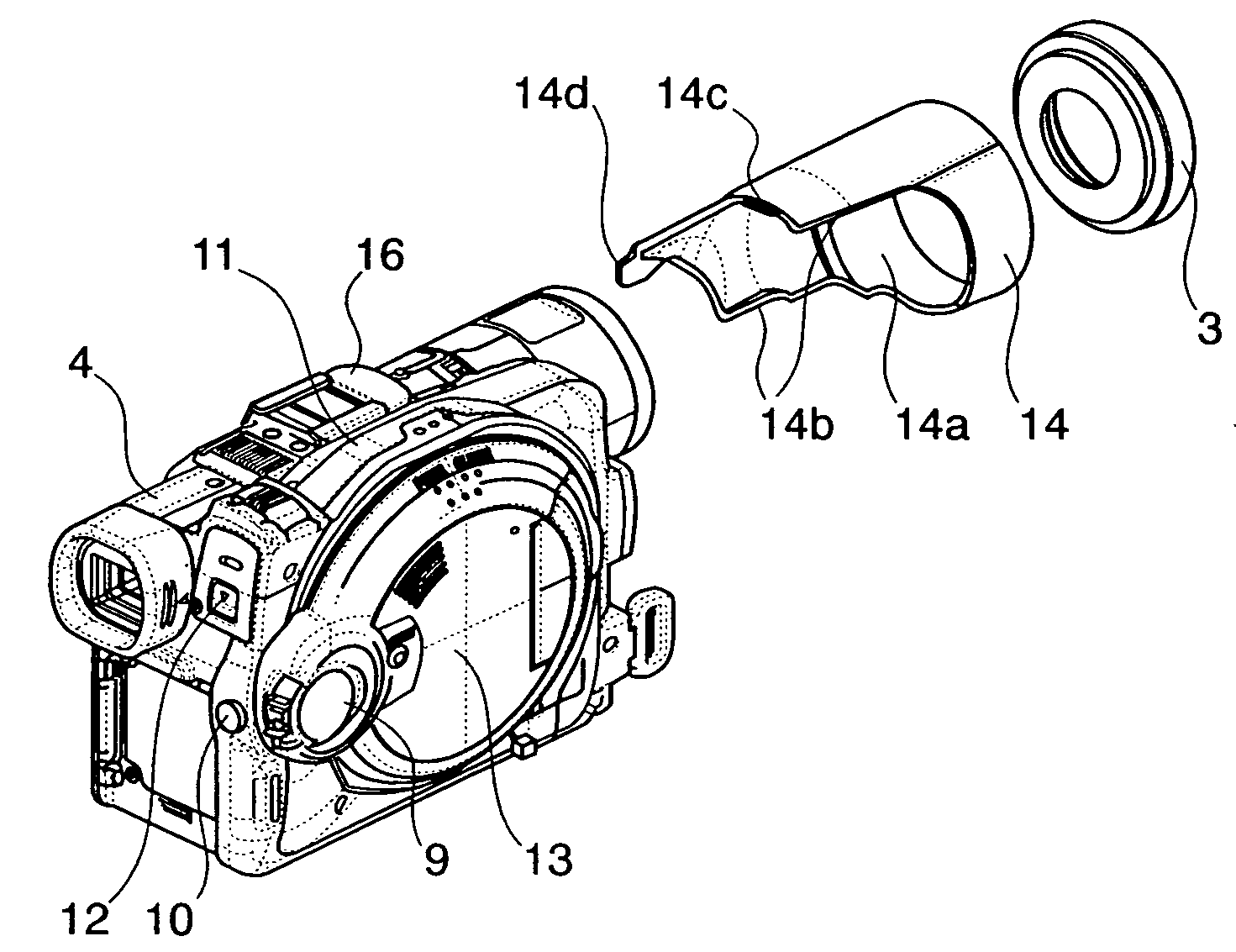
[0012] In one embodiment, a video camera comprises a lens unit to receive images to be captured; a display device to display the captured images; a main camera body; and one or more exterior decorative components, each being configured to be removed and replaced with a corresponding decorative component having different appearance, wherein one of the exterior decorative components includes a body and a first protrusion that extends outwardly from the body, and wherein the main camera body defines a first recess that is configured to receive the first protrusion. The exterior decorative component has a second protrusion having a width of no more than 5 millimeter. The second protrusion has a backend that extends no more than 0.7 millimeter from a backend of the body of the one exterior component.
[0013] In another embodiment, a video camera comprises a lens unit to capture images; a display device to display the captured images; a main camera body; and at least one exterior decorative component that is configured to be removed and replaced with a corresponding decorative component having different appearance, wherein the at least one exterior decorative components includes a body and a first protrusion that extends outwardly from the body, wherein the main camera body defines a first recess that is configured to receive the first protrusion, and wherein the one exterior component defines a groove between the body of the exterior component and the first protrusion, the groove being configured to make the first protrusion less visible to human eyes.
[0014] In yet another embodiment, a lens cover for a video camera includes a body having a cylindrical upper portion and a lower portion; a holding projection extending outward from the lower portion of the body, the holding projection being configured to be received by a recess defined on a case of the video camera; a groove defined between the lower portion of the body and the holding projection to make the holding projection less visible when the holding projection is inserted into the recess of the case, wherein the lens cover is a removable, exterior decorative component of the video camera.

Problems solved by technology

However, color-variation development has not been successfully applied to video cameras.
Therefore, a part-changing system that permits a user to change the exterior panels of a procured portable telephone cannot be directly applied to the video camera.
Therefore, the painted exterior cases having complicated shapes may have an undesirable, complicated appearance.
However, since the exterior cases of the video camera have complicated shapes, paint is liable to stick to parts covered with the painting mask.
Therefore, a user buying a camera is able to select merely a color and the feel of quality and is unable to change the color and the feel of quality of the camera after buying the camera.

Method used


Image

  • Video camera
  • Video camera
  • Video camera

Examples


Embodiment Construction

[0029] Video cameras in preferred embodiments according to the present invention will be described with reference to FIGS. 1 to 9.

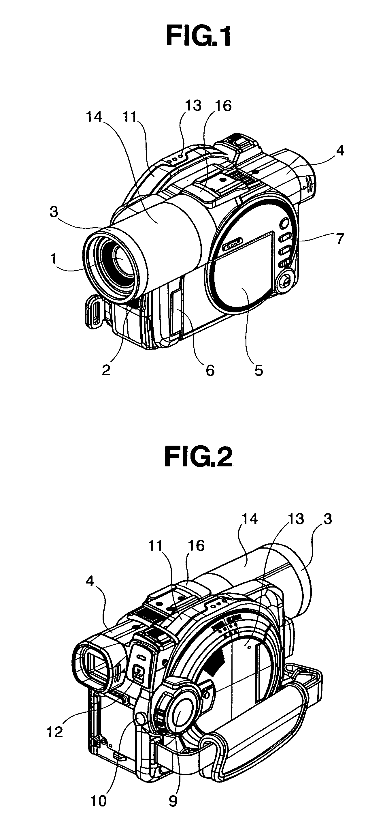
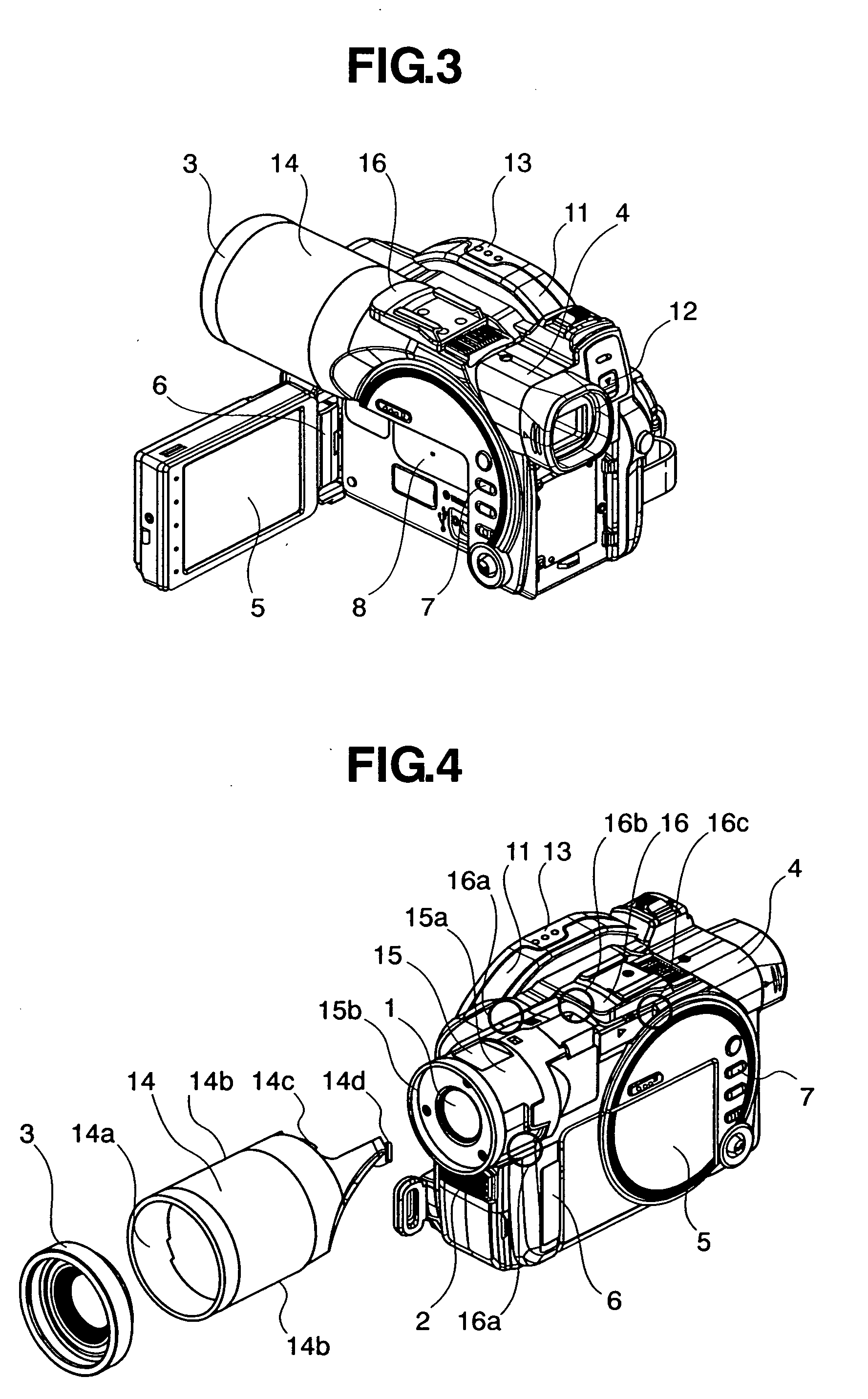
[0030] A video camera in a first embodiment according to the present invention will be described with reference to FIGS. 1 to 3 and 6. FIG. 1 is a front perspective view of the video camera, FIG. 2 is a rear perspective view of the video camera, FIG. 3 is a perspective view of the video camera in a state where an LCD (liquid crystal display) for displaying images taken by the video camera is unfolded, and FIG. 6 is an exploded perspective view of the video camera.

[0031] The video camera in the first embodiment has a front unit including a lens unit 1, a microphone unit 2, a lens cover 14, n, and a front case 15, and holding the lens cover 14. A liquid crystal display unit (or display device) includes an LCD 5, an LCD support 6, a main case 16, an L case 20 and a base plate 21. A grip unit includes a grip 11, a grip cover 13, a drive cover 17 and a drive...


PUM


Abstract

A video camera comprises a lens unit to receive images to be captured; a display device to display the captured images; a main camera body; and one or more exterior decorative components, each being configured to be removed and replaced with a corresponding decorative component having different appearance, wherein one of the exterior decorative components includes a body and a first protrusion that extends outwardly from the body, and wherein the main camera body defines a first recess that is configured to receive the first protrusion.

Description

CROSS-REFERENCES TO RELATED APPLICATIONS [0001] This application claims priority to Japanese Patent Application No. 2003-428628, filed on Dec. 25, 2003. BACKGROUND OF THE INVENTION [0002] The present invention relates to a video cameral provided with replaceable external decorative members. [0003] Color-variation development for electronic devices has been pursued extensively by various entities to produce electronic devices of the same model in different colors or to provide different exterior panels for electronic devices of the same model to enable users to select desired exterior panels, to satisfy the tastes and interests of different users. [0004] The color-variation development has been successfully applied to portable telephones and the like, as described in JP-A No. 2002-125022 and JP-A No. 2003-143268. However, color-variation development has not been successfully applied to video cameras. [0005] This is in part due to the different configuration used for typical video cam...

Claims


Application Information

Patent Timeline
Patent Type & Authority Applications(United States)
IPC IPC(8): G03B17/02G03B11/04H04N5/225
CPCH04N5/2252H04N23/51
Inventor ISHIKURO, SHINICHI
Owner HITACHI LTD
Learn More