Vehicle lighting apparatus

a technology of vehicle lighting and lighting components, which is applied in the direction of lighting and heating equipment, lighting support devices, transportation and packaging, etc., can solve the problems of small number of mounting components, reduce manufacturing man-hours, and simplify the structure of the lamp body, the lamp unit, or the brack

Active Publication Date: 2005-06-30
KOITO MANUFACTUARING
View PDF8 Cites 23 Cited by
  • Summary
  • Abstract
  • Description
  • Claims
  • Application Information

AI Technical Summary

Benefits of technology

[0016] Since, in the lighting apparatus of the embodiment of the invention, the horizontal driving mechanism and the vertical driving mechanism are integrated with each other, therefore, the manufacturing man-hours is small. Also, the number of mounting components is small. Moreover, since the driving mechanism can be mounted in the lamp body at only one portion, the structure of the lamp body, the lamp unit, or a bracket can be simplified. Thus, the manufacturing cost of these members can be reduced.
[0017] Further, according to the embodiment of the invention, the horizontal driving mechanism and the vertical driving mechanism are provided in a single housing. Thus, the man-hours required to assemble the driving mechanisms can be reduced to thereby decrease the manufacturing cost thereof.
[0018] Furthermore, according to the embodiment of the invention, the horizontal driving mechanism and the vertical driving mechanism are supported tiltably with respect to the lamp body. Thus, the driving mechanism do not protrude toward the rear of the lamp body. Consequently, the depth of the lamp can be reduced.
[0019] Also, the assembling of the lamp unit can be performed in front thereof. Thus, favorable assembling efficiency is obtained. This contributes to reduced cost.
[0020] Moreover, according to the embodiment of the invention, the supply of electric power and / or a control signal to the horizontal driving mechanism and the vertical driving mechanism is performed through a single connector. Thus, the number of components (for instance, a connector) can be reduced. Also, wiring in the lamp can be simplified.

Problems solved by technology

Also, the number of mounting components is small.

Method used


Image

  • Vehicle lighting apparatus
  • Vehicle lighting apparatus
  • Vehicle lighting apparatus

Examples


first embodiment

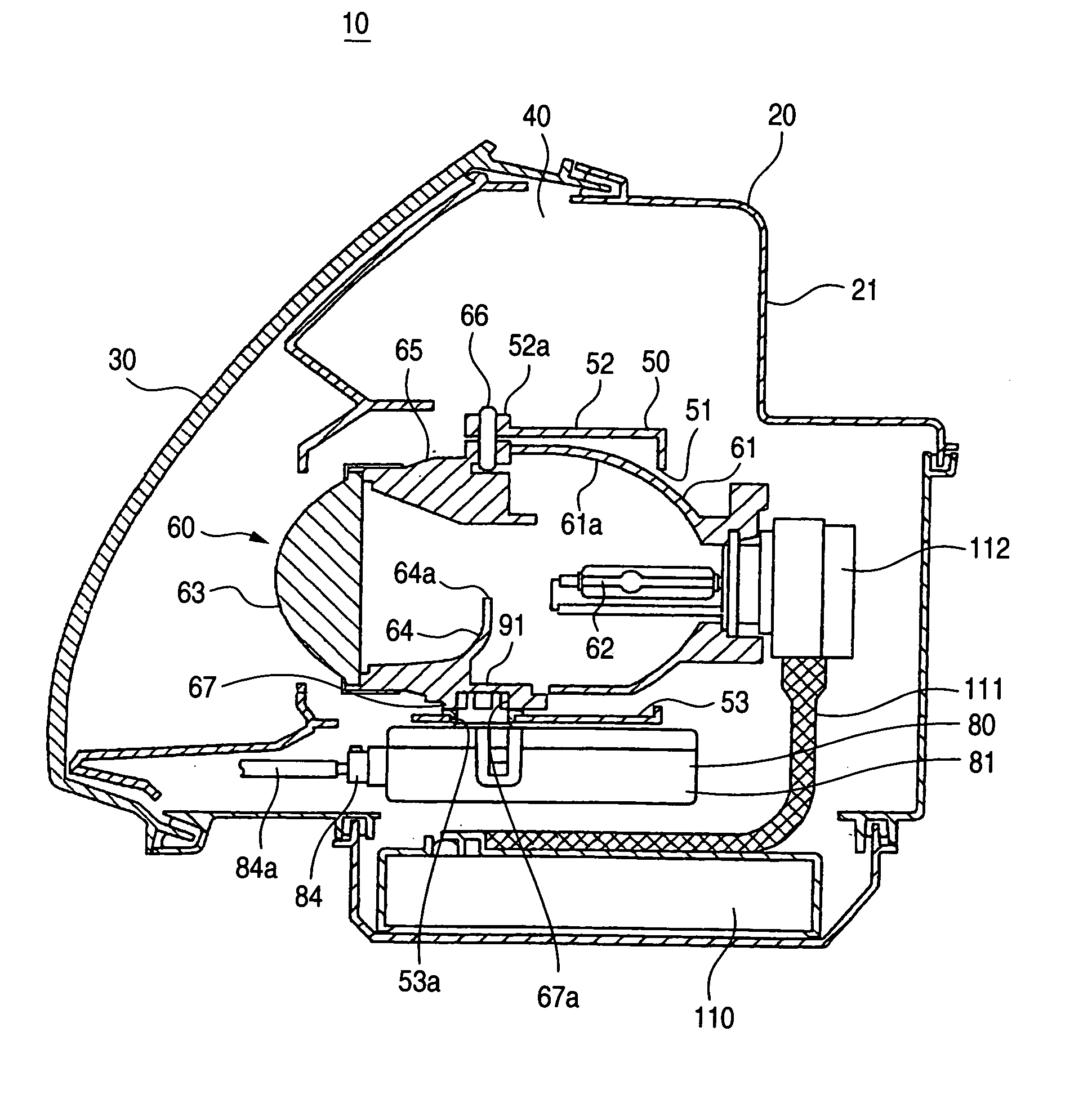
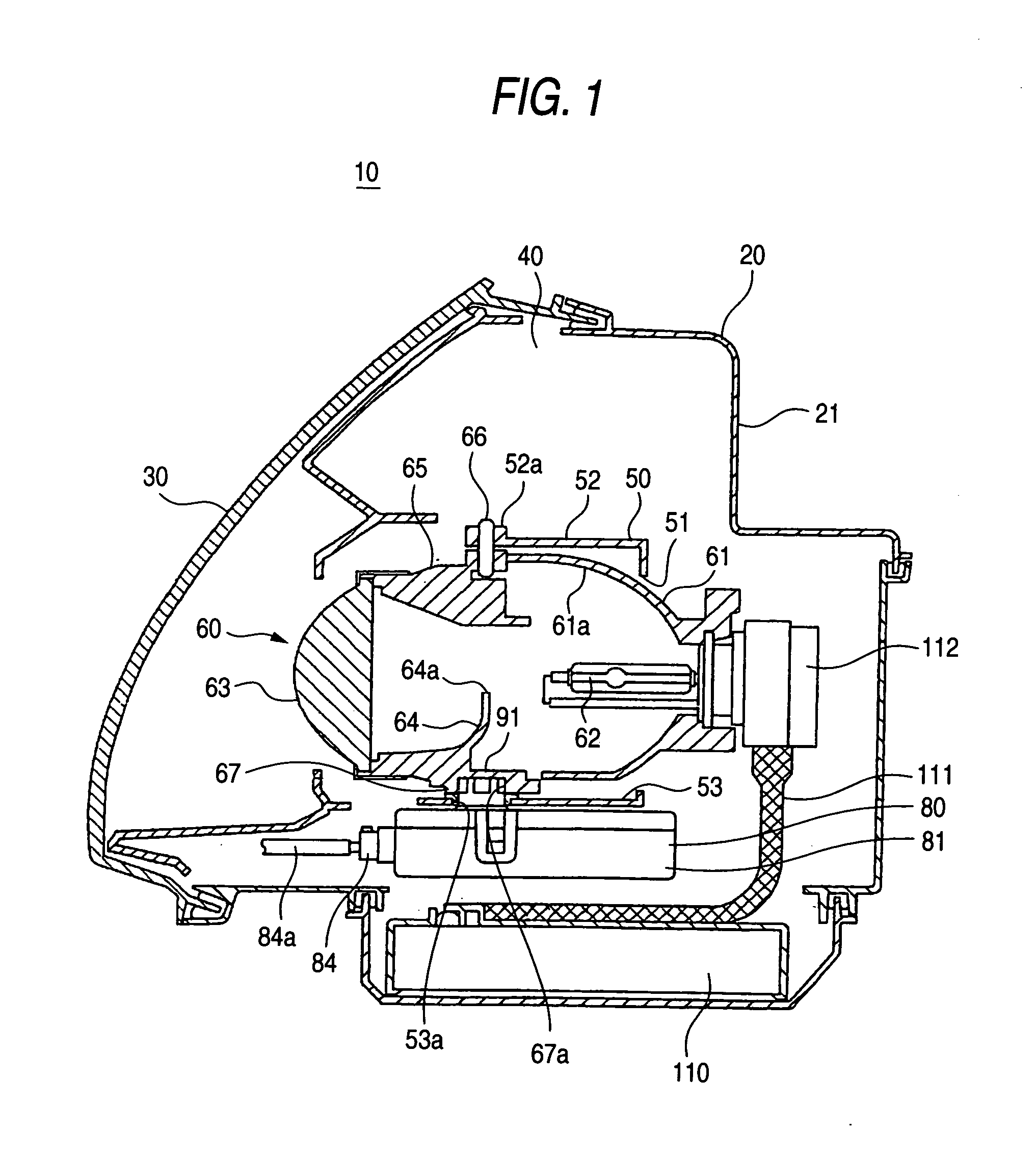
[0029] FIGS. 1 to 5 show a first embodiment of the invention, which is applied to a vehicle headlamp.

[0030] As is seen from FIG. 1, a vehicle headlamp 10 has a lamp body 20 having a concave portion frontwardly opened. A lamp chamber 40 is formed by covering the front opening of the lamp body 20 with a transparent cover 30.

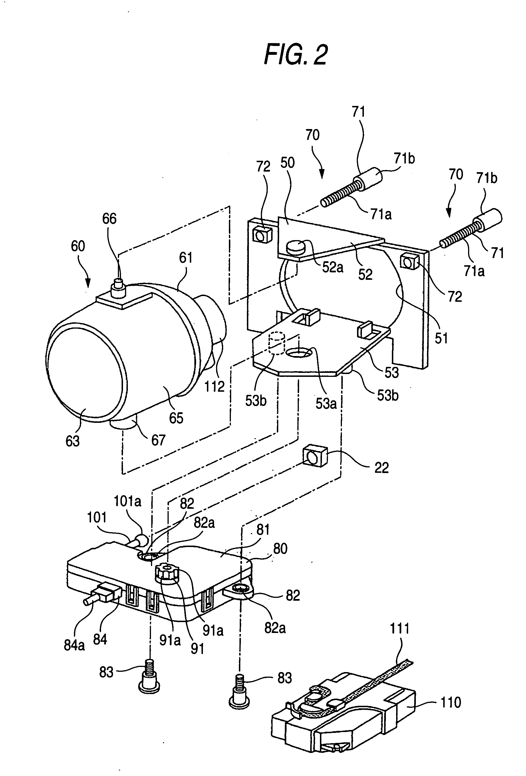
[0031] As is seen from FIGS. 1 and 2, a bracket 50 supported tiltably with respect to the lamp body 20 is disposed in the lamp chamber 40. A lamp unit 60 is horizontally tiltably supported by the bracket 50. The bracket 50 has upper two points horizontally spaced apart from each other, which are supported by turn-supporting-point portions 70, 70, and also has a lower part thereof supported through a biaxial actuator (to be described later).

[0032] The turn-supporting-point portion 70 comprises an adjusting shaft 71, which is rotatably supported on a rear surface wall 21 of the lamp body 20, and a nut element 72 supported by the bracket 50. The adjusting shaft 71 ...

second embodiment

[0064]FIG. 6 shows a primary part of a second embodiment of the lighting apparatus according to the invention.

[0065] A lamp unit 210 is fixedly attached to a bracket 220.

[0066] The lamp unit 210 has a reflector 211 and a projection lens 212, and converges light outputted from a light source bulb (not shown). Moreover, the lamp unit 210 irradiates the light frontwardly as a beam having the light distribution pattern, the upper edge of which is limited by a shade placed at a light converging region, by using the projection lens 212.

[0067] The bracket 220 is tiltably supported by the lamp body (not shown) through a single turn-supporting-point portion 230 and a biaxial actuator 240.

[0068] The turn-supporting-point portion 230 comprises a supporting-point shaft 231 fixed to the rear surface wall of the lamp body, and also comprises a sphere receiving element 232 supported on one side portion of the bracket 220. The turn-supporting-point portion 230 is configured by rotatably fitting...


PUM


Abstract

A lamp body 20 includes a lamp unit 60 whose irradiation direction is changed according to a running state of a vehicle, a horizontal driving mechanism 90 for horizontally changing the irradiation direction, and a vertical driving mechanism 100 for vertically changing the irradiation direction. The horizontal driving mechanism and the vertical driving mechanism are integrated with each other, so that a lighting apparatus 10 can be mounted in a vehicle by using only a small mounting space. Moreover, the lighting apparatus 10 needs only small numbers of components and mounting man-hours.

Description

[0001] This application claims foreign priority based on Japanese patent application No. JP-2003-429231, filed on Dec. 25, 2003, the contents of which is incorporated herein by reference. BACKGROUND OF THE INVENTION [0002] The present invention relates to a novel lighting apparatus of a vehicle. More particularly, the invention relates to a lighting apparatus having a horizontal driving mechanism for changing an irradiation direction in the horizontal direction and a vertical driving mechanism for changing the irradiation direction in the vertical direction, and to a technique for simplifying a structure. [0003] There has been a lighting apparatus of a vehicle adapted so that an irradiation direction thereof is changed according to a running state of the vehicle. [0004] For example, sometimes, the irradiation direction of a vehicle headlamp becomes excessively upward or downward in response to change in a load. In such a case, it is necessary to timely correct the irradiation direct...

Claims


Application Information

Patent Timeline
Patent Type & Authority Applications(United States)
IPC IPC(8): B60Q1/076F21V23/02F21V27/00
CPCB60Q1/076F21V27/00F21V23/026F21S48/1186F21S41/17
Inventor TAJIMA, KEIICHITAKIGUCHI, TSUTOMUMOCHIZUKI, KAZUMATAKII, NAOKI
Owner KOITO MANUFACTUARING
Why Eureka
Try Eureka