Optical sensor having light projecting prism

a technology of optical sensors and prisms, applied in the field of optical sensors, can solve the problems of deterioration of detection sensitivity and accuracy in some object positions, comparatively high cost of glass lenses, and inability to detect sizes, etc., and achieves the effect of accurate information detection, low cost, and simple structur

Inactive Publication Date: 2006-04-25
KEYENCE
View PDF13 Cites 7 Cited by
  • Summary
  • Abstract
  • Description
  • Claims
  • Application Information

AI Technical Summary

Benefits of technology

[0028]The light rays passing through the opening and entering the light detection means are partly diffusively reflected by the halftone dots of the halftone dot filter and partly pass through the remaining part of the halftone dot filter except the halftone dots. As the dot density of the halftone dot filter varies, in steps or linearly, so as to make an intensity distribution of incoming light rays approximately uniform, the light rays incident upon the light receiving element are uniform in intensity. This leads to accurate detection of information on the subject.
[0029]Further, as the light opaque member with an elongated opening formed therein restrains a beam width of the light rays that enter the housing through the transparent member, the li

Problems solved by technology

This possibly leads to deterioration of the detection sensitivity and accuracy in some object positions and, in addition, to a failure to detect sizes of some of the subjects 105 in subject positions even though the subjects 105 are the same in size.
In order to provide a wide beam of light rays, it is essential to use a collimator lens having a large aperture, desirably a glass lens, that is comparatively expensive due to the difficulty in precise surface finishing.
However, the parallel laser beam linear sensor in which a laser diode is used as the light emitting element 101 is inevitably bulky and expensive.
In cons

Method used


Image

  • Optical sensor having light projecting prism
  • Optical sensor having light projecting prism
  • Optical sensor having light projecting prism

Examples


Embodiment Construction

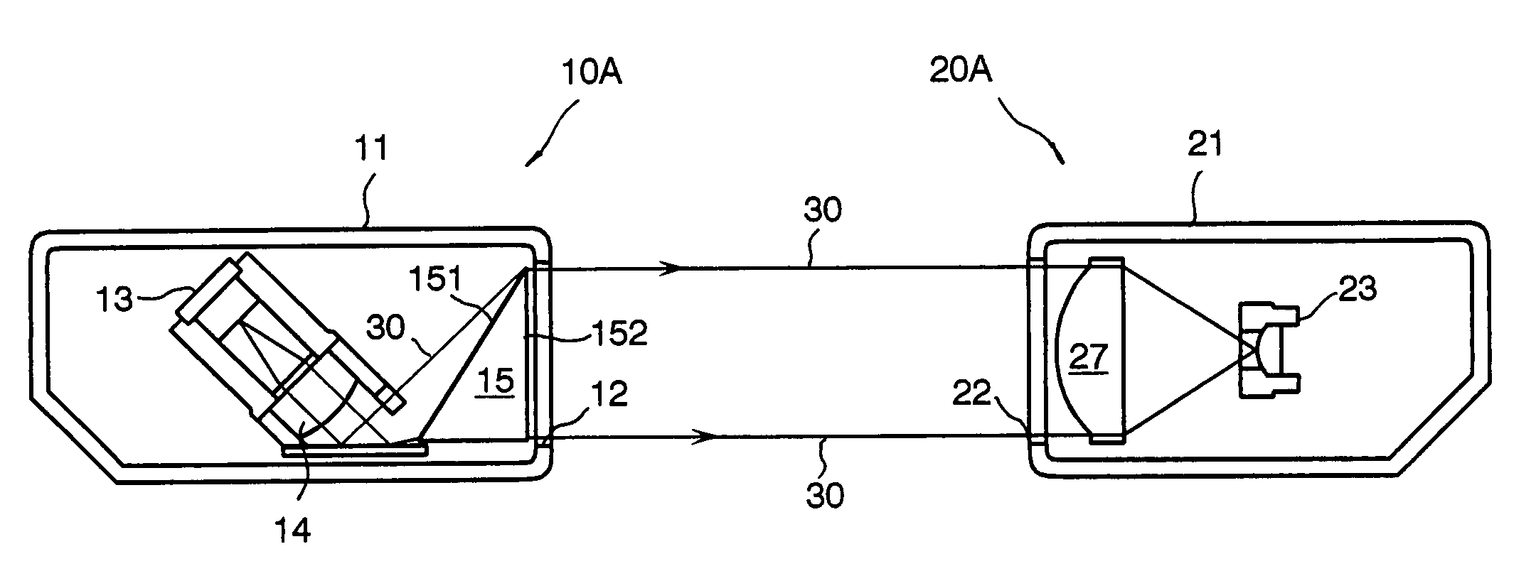
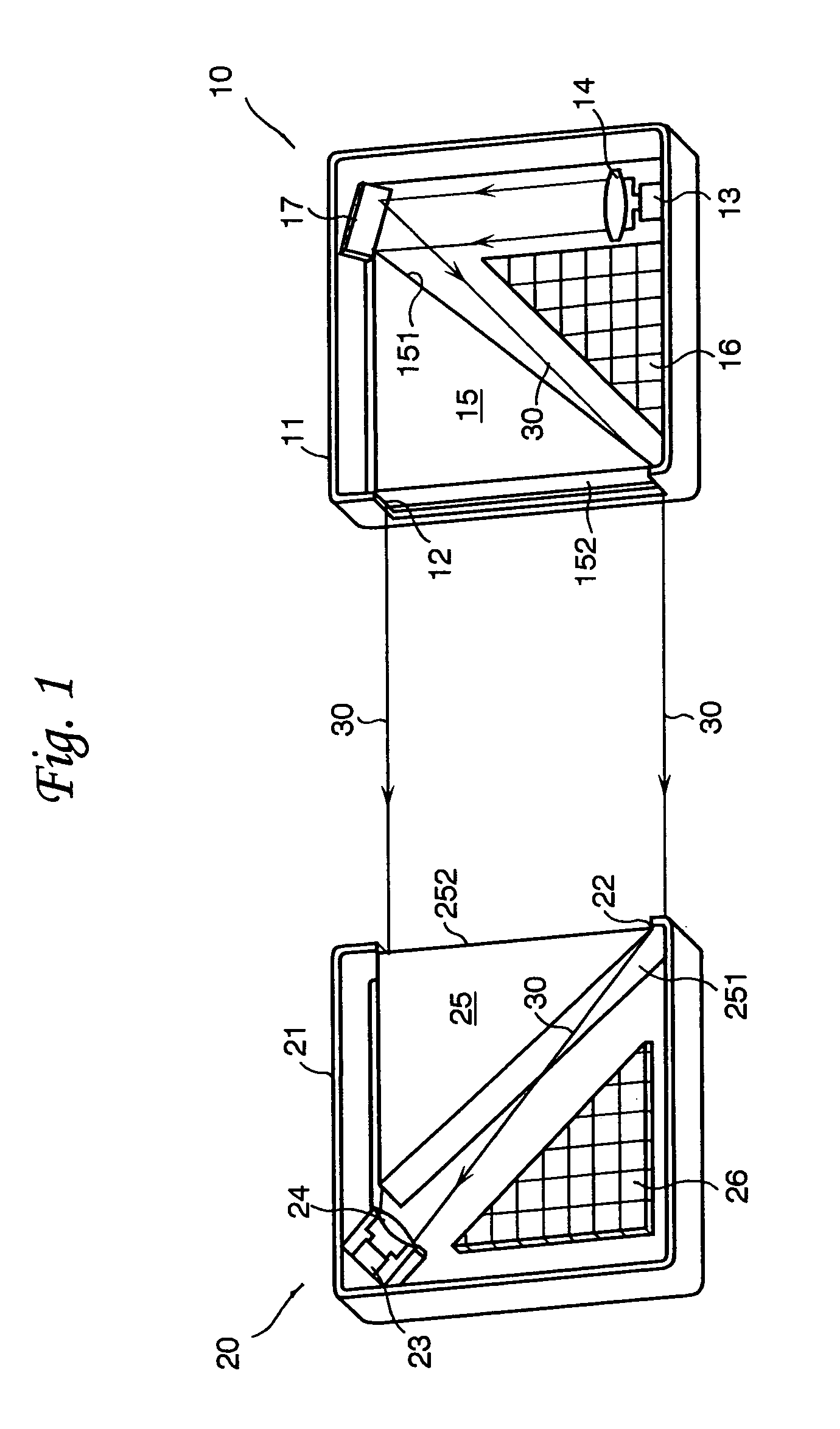
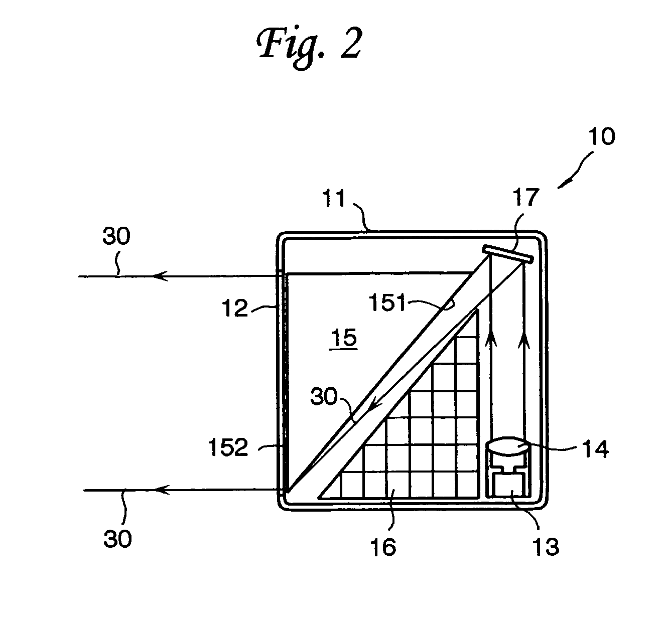
[0055]Referring to the drawings in detail, and, in particular, to FIG. 1 showing an internal structure of an optical sensor according to an embodiment of the present invention, the optical sensor comprises a light projection unit 10 and a light detection unit 20. The light projection unit 10 has a generally square housing 11 with an elongated window 12 formed in one of the walls thereof. In the housing 11, there are arranged a light source, namely a light emitting element 13 such as a laser diode, a collimator lens 14, a light projecting prism 15 made of a right angle glass block, a circuit board 16 having a right triangle shape on which a drive circuit for the light emitting element 13 is formed, and a reflecting mirror 17. Specifically, the light emitting element 13 is positioned in one of the corners of the housing so as to emit light rays. The collimator lens 14 collimates the light rays from the light emitting element 13 and directs the light rays toward the reflecting mirror 1...


PUM


Abstract

An optical sensor projects light rays emanating from a light emitting element that are collimated by a lens and reflected by a mirror and then directed to a light projecting prism. The collimated light rays incident upon the prism are refracted at an incident surface and come out from the prism through a light exit surface so as thereby to be projected into the field of detection. Light rays passing through the field of detection are directed to a light receiving prism. The light rays incident upon the light receiving prism through a light incident surface are reflected by a light exit surface and then come out from the light receiving prism. The outgoing light rays are received and converted into an electric signal by a light receiving element.

Description

BACKGROUND OF THE INVENTION[0001]1. Field of the Invention[0002]The present invention relates to an optical sensor for projecting light rays into a field of detection and detecting information on a subject in the field of detection based on light rays returning from the field of detection.[0003]2. Discussion of the Related Art[0004]There have been various optical sensors such as photoelectric sensors and optical scanners for detecting information on a subject or subjects such as the presence or absence of the subject in a specified field of detection and measurements of the subject, a position of the subject, a configuration of the subject, a distance between the subjects, or a graphical or pictorial image applied to the subject by projecting light rays into the field of detection and detecting an intensity distribution of the light rays that are reflected by or transmit through the subject in the field of detection. Before describing the present invention in detail, reference is ma...

Claims


Application Information

Patent Timeline
IPC IPC(8): G01N21/64G01B11/02G01J1/02G01J1/04G01V8/14G02B5/04G08B13/183
CPCG01V8/14G08B13/183G02B5/04
Inventor TORII, TOMONARI
Owner KEYENCE
Why Eureka
Try Eureka