
Clip clamping mechanism of pressure fixture and pneumatic caliper having the same

a technology of pressure fixture and clamping mechanism, which is applied in the direction of metal-working hand tools, metal-working wire tools, metal-working apparatus, etc., can solve the problems of short service life and high manufacturing cost, and achieve reliable connection, reduced cost, and small manufacturing.

Active Publication Date: 2015-01-15
YUEQING DONGBO ELECTROMECHANICAL
View PDF3 Cites 8 Cited by
  • Summary
  • Abstract
  • Description
  • Claims
  • Application Information

AI Technical Summary

Benefits of technology

The disclosed patent aims to provide a clip clamping mechanism for a pressure fixture that reduces manufacturing costs, is resistant to damage, and has a long service life. The mechanism uses a single fixed shaft to connect two clips, allowing for a butting clamp function. The use of air as a power source provides stability and reliability, while a piston assembly ensures smooth transmission of propulsion. Additionally, the mechanism eliminates the need for an extra sealing element and reduces costs by ensuring a reliable connection between two sets of piston assemblies during assembly.

Problems solved by technology

However, in existing designs known in conventional art, since the wedge-shaped propulsion piece is pushed in between two strut portions to stretch the two strut portions, and the first clip and the second clip are mounted on the clamp base through two fixed shafts to realize a butting clamping function, two hinging joints are needed, thus manufacturing cost is high, damage is easily caused and the service life is short.

Method used


Image

  • Clip clamping mechanism of pressure fixture and pneumatic caliper having the same
  • Clip clamping mechanism of pressure fixture and pneumatic caliper having the same
  • Clip clamping mechanism of pressure fixture and pneumatic caliper having the same

Examples


embodiment 1

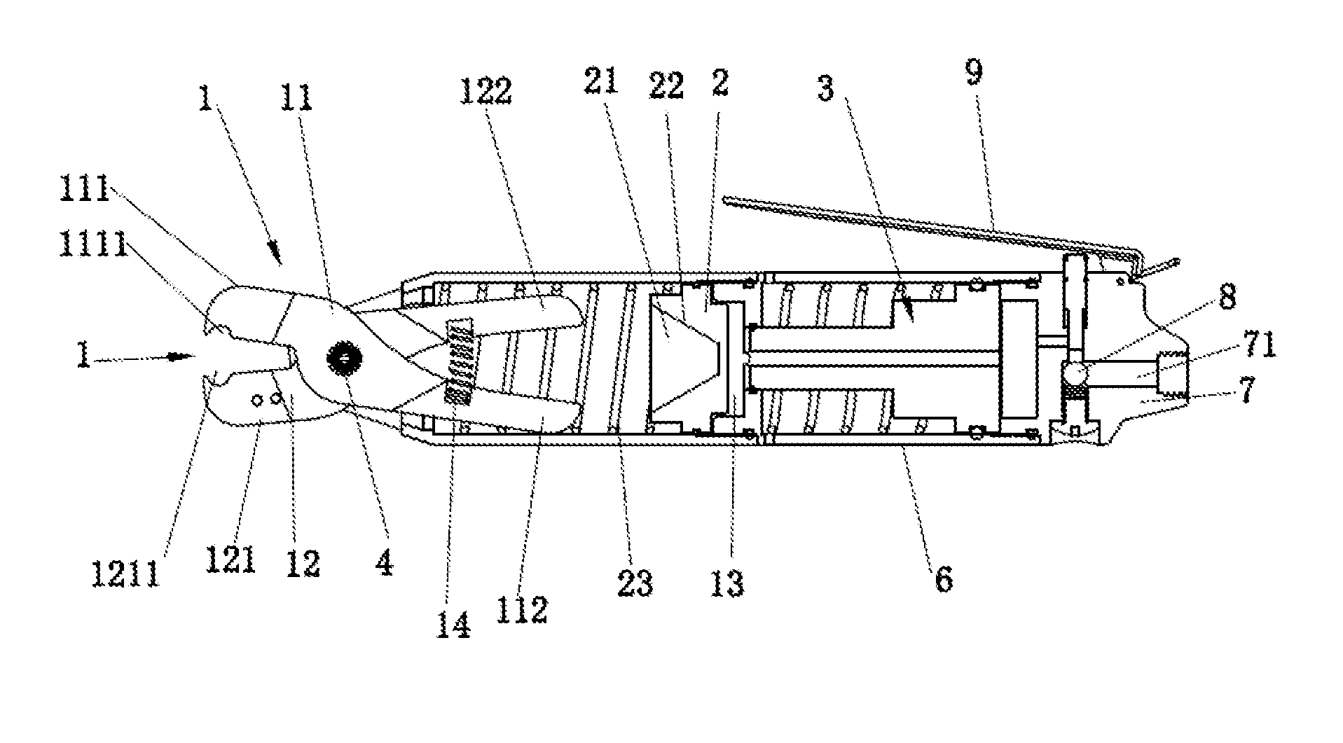
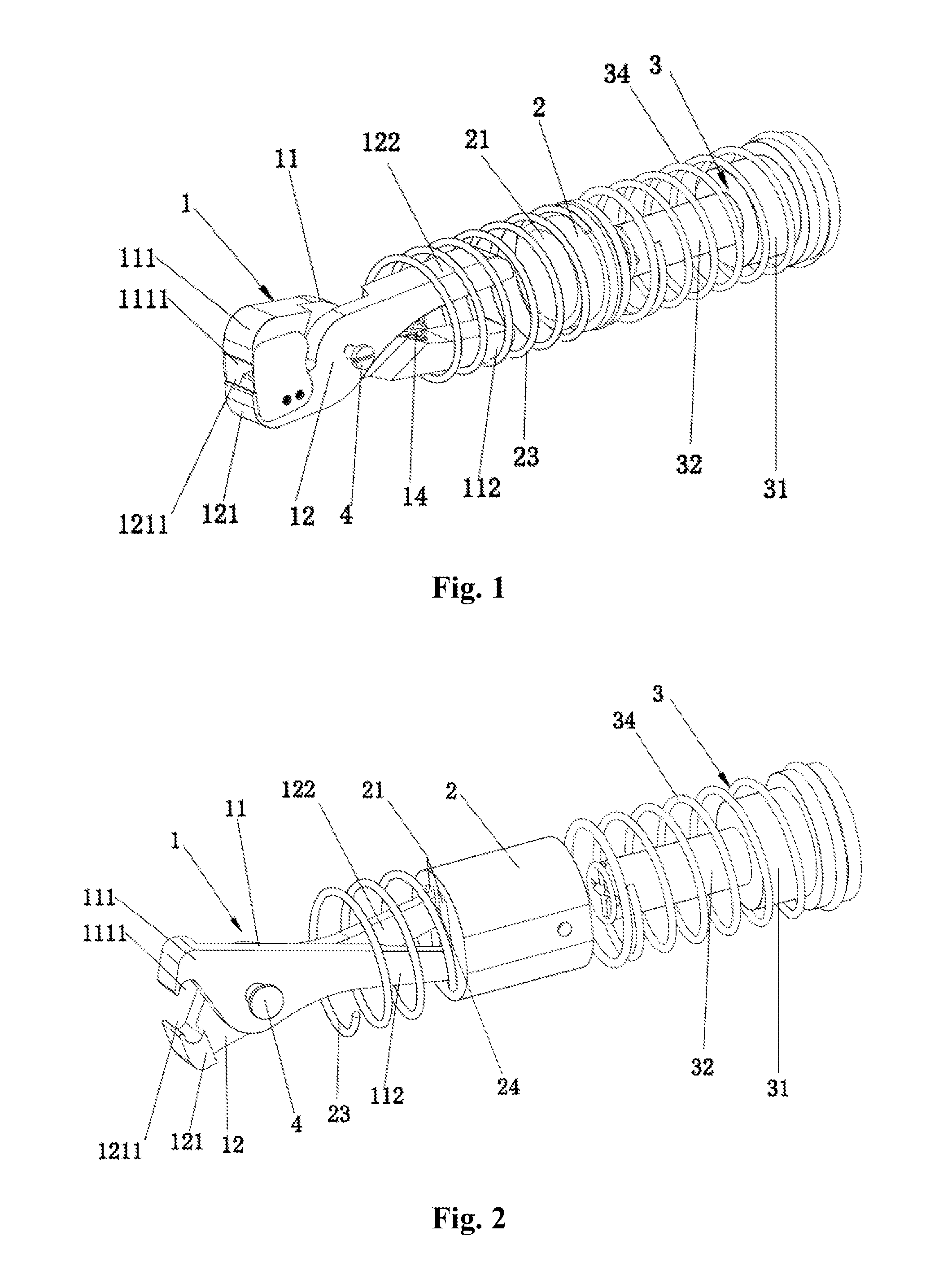
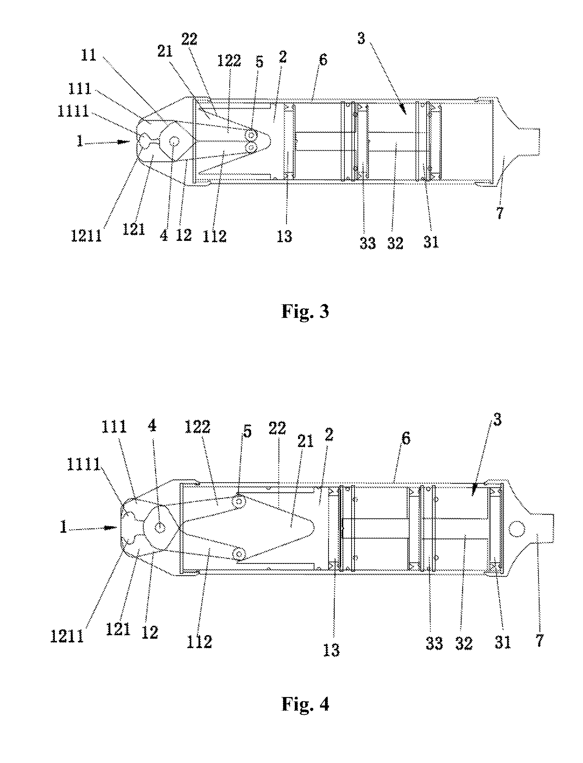
[0039] the clip 1 and the propulsion 2 are arranged along the same axial direction; both the rear arm 112 of the first clip 1 and the rear arm 122 of the second clip 12 are arranged in one accommodation cavity 21, which is arranged as a triangular structure along the cross section of the axial line; preferably, the accommodation cavity 21 selects a conical structure; the wedge-shaped side wall 22 presents a straight line; the accommodation cavity 21 presents a circular arc shrinking to the small end from the big end (it should be noted here that the wedge-shaped side wall 22 also can present a circular arc, which can be a bulged circular arc; when the wedge-shaped sidewall 22 is a bulged circular arc, the clamping speed of the clip 1 first increases and then decreases in the condition that the propulsion piece 2 moves at a constant speed; when clamping articles such as hoop, ring washer, pin, cable terminal and cable clip, the clamping speed slows down near the end of the lamping ac...

embodiment 2

[0041] the accommodation cavity is provided with a separator plate 24 for separating the rear arm of the first clip and the rear arm of the second clip.

[0042]Through the above technical scheme, another structure of the propulsion piece 2 is disclosed, that is, the accommodation cavity 21 is provided with a separator plate 24, which divides the cavity 21 into two chambers so that the two rear arms 112, 122 are separated from each other and have no impact on each other; thus, the pressure fixture of this structure has a stable extrusion force.

[0043]A pneumatic caliper is provided (it should be noted here that any one clip clamping mechanism of the pressure fixture described in claim 1 to claim 2 can be applied to other pressure fixtures; the applicant of this patent selects to apply the clip clamping mechanism to a pneumatic caliper, so as to extrude or clamp a hoop), which has any one clip clamping mechanism of the pressure fixture described in claim 1 to claim 2, including: a cylind...


PUM

PropertyMeasurementUnit
pressureaaaaaaaaaa
thrustaaaaaaaaaa
extrusion forceaaaaaaaaaa

Abstract

A clip clamping mechanism of a pressure fixture, which the clip comprises a fixedly mounted shaft, and a first clip and a second clip hinged through the fixed shaft. Two ends of the first clip and the second clip corresponding to the hinging joint form respectively a front arm, and a rear arm in linkage with a propulsion piece, wherein the propulsion piece is provided with an accommodation cavity for mounting the rear arm; and the accommodation cavity is provided with a wedge-shaped sidewall for butt junction and slip fit with the rear arm; one end of the accommodation cavity close to the front arm is a big end with opening, while the other end far away the front arm is a small end. The first clip and the second clip achieve a transmission connection through one fixed shaft only to realize butting clamp.

Description

FIELD OF THE INVENTION[0001]The disclosure relates to a clamping mechanism and a pressure fixture having the same, and in particular to a clip clamping mechanism of a pressure fixture and a pneumatic caliper having the same.BACKGROUND OF THE INVENTION[0002]Pneumatic calipers used for extruding and clamping hoop, ring washer, pin, cable terminal, cable clip and the like are well known. Pneumatic calipers are particularly familiar in automobile industry, which are used to clamp ring washers onto pipe joint, coupling shaft and similar pieces during the assembling of inner tube and corrugated pipe.[0003]Patent literature records a European patent document of which the application number is 00112559.0 and which then enters China through Patent Cooperation Treaty (PCT) and has a Chinese authorization proclamation No. of CN1264650C, and in which a device for pneumatic operation tool and a pneumatic clamp having the same are provided; this patent provides a pressure medium joint controlled ...

Claims


Application Information

Patent Timeline
Patent Type & Authority Applications(United States)
IPC IPC(8): B25B27/14
CPCB25B27/146Y10T29/53717B25B25/005
Inventor YOU, YIXIAN
Owner YUEQING DONGBO ELECTROMECHANICAL
Learn More